4 tbs data source, Tbs data source, Table 19. tbs configurations using on-chip data – Cirrus Logic CS5376A User Manual
Page 65: Cs5376a
CS5376A
DS612F4
65
Loopback - LOOP
Enables digital loopback from the TBS output to
the MDATA inputs.
Run - RUN
Enables the test bit stream generator.
Data Delay - DDLY[5:0]
Programs full period delays for TBSDATA, up to a
maximum of 63 bits.
Gain - TBSGAIN[23:0]
Scales the amplitude of the sine wave output. Max-
imum 0x04FFFF, nominal 0x04B8F2.
17.4 TBS Data Source
Data to create test signals is loaded into digital fil-
ter memory by configuration commands. The on-
chip sine wave data is suitable for most tests,
though custom data is required to support custom
signal frequencies. See “EEPROM Configuration
Commands” on page 28 or “Microcontroller Con-
figuration Commands” on page 35 for information
about programming TBS data.
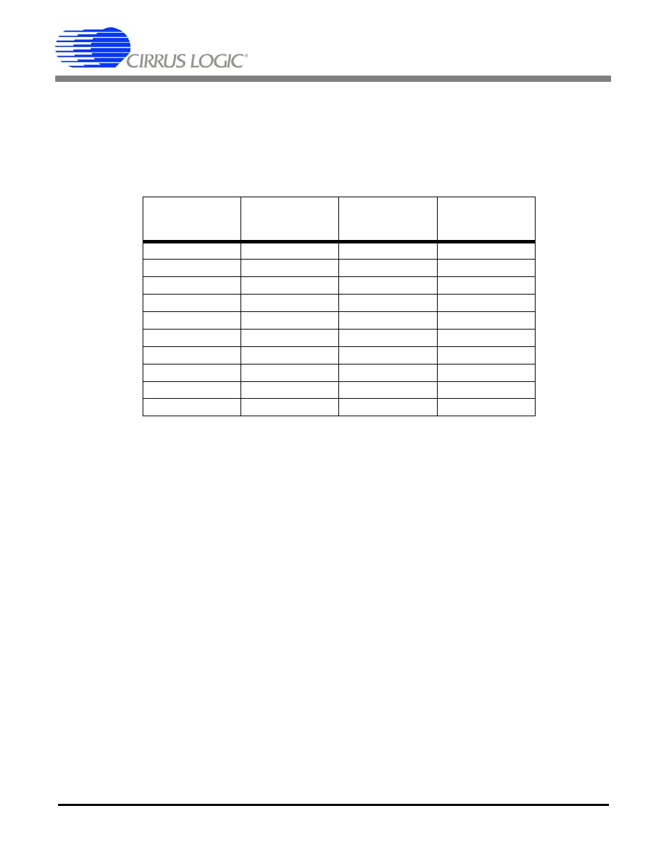
TBS ROM Data
An on-chip 24-bit 1024 point digital sine wave is
stored on the CS5376A. When selected by the
‘Write TBS ROM Data’ configuration command,
the TBS generator can produce the test signal fre-
quencies listed in Table 19. Additional discrete test
frequencies and output rates can be programmed
with the on-chip data by varying the interpolation
factor and output rate.
Custom TBS Data
If a required test frequency cannot be generated us-
ing the on-chip test bit stream data, a custom data
Test Bit Stream Characteristic Equation:
(Signal Freq) * (# TBS Data) * (Interpolation + 1) = Output Rate
Example:
(31.25 Hz) * (1024) * (0x07 + 1) = 256 kHz
Signal
Frequency
(TBSDATA)
Output
Rate
(TBSCLK)
Output Rate
Selection
(RATE)
Interpolation
Selection
(INTP)
10.00 Hz
256 kHz
0x4
0x18
10.00 Hz
512 kHz
0x5
0x31
25.00 Hz
256 kHz
0x4
0x09
25.00 Hz
512 kHz
0x5
0x13
31.25 Hz
256 kHz
0x4
0x07
31.25 Hz
512 kHz
0x5
0x0F
50.00 Hz
256 kHz
0x4
0x04
50.00 Hz
512 kHz
0x5
0x09
125.00 Hz
256 kHz
0x4
0x01
125.00 Hz
512 kHz
0x5
0x03
Table 19. TBS Configurations Using On-chip Data