Figure 45. hardware configuration register config, Cs5376a, 1 config : 0x00 – Cirrus Logic CS5376A User Manual
Page 87: Bit definitions
CS5376A
DS612F4
87
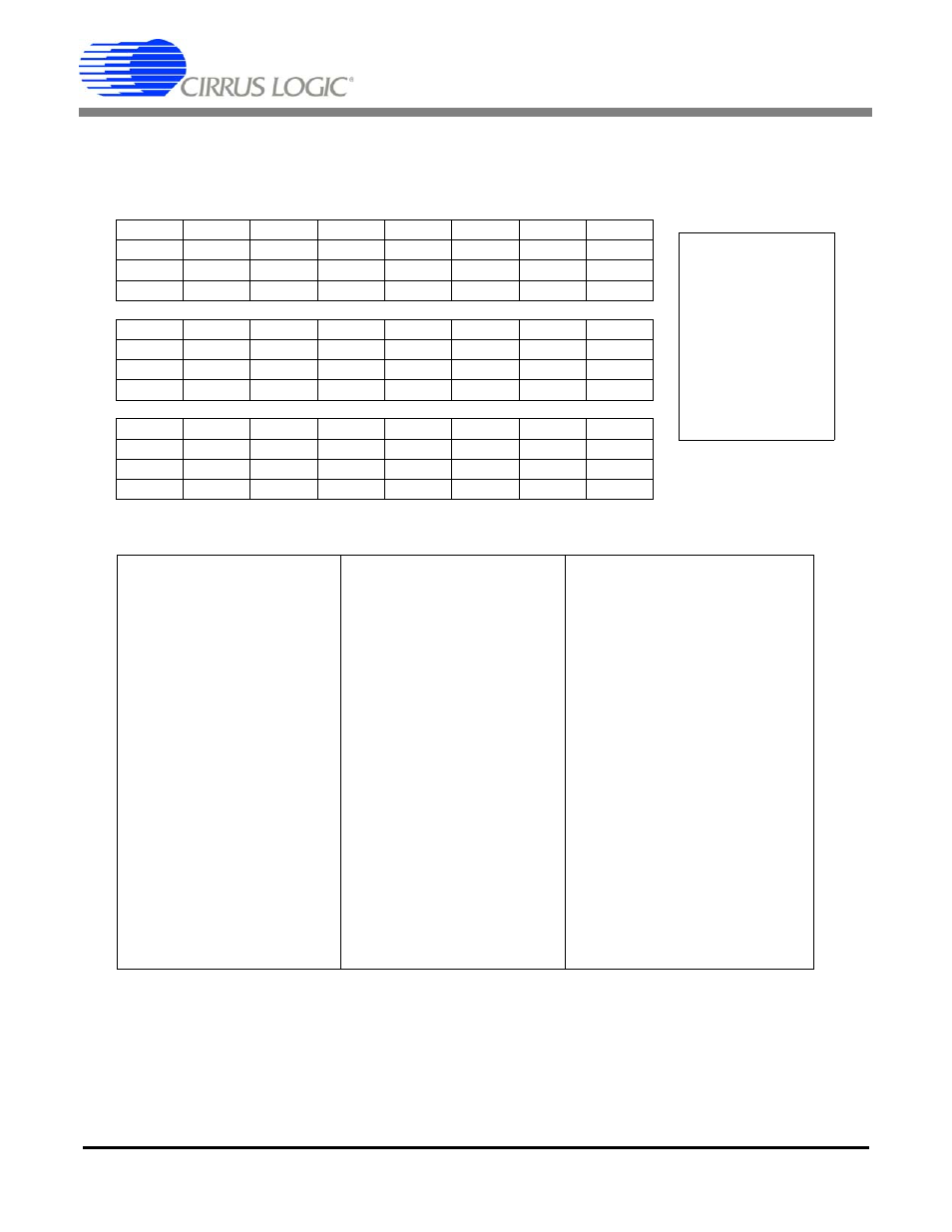
23.2.1
CONFIG : 0x00
(MSB)23
22
21
20
19
18
17
16
--
--
--
--
--
DFS2
DFS1
DFS0
R/W
R/W
R/W
R/W
R/W
R/W
R/W
R/W
0
0
0
0
0
1
0
1
15
14
13
12
11
10
9
8
--
--
--
--
--
MCKFS2
MCKFS1
MCKFS0
R/W
R/W
R/W
R/W
R/W
R/W
R/W
R/W
0
0
0
0
0
1
0
0
7
6
5
4
3
2
1
(LSB)0
--
--
MCKEN2
MCKEN
MDIFS
--
BOOT
MSEN
R/W
R/W
R/W
R/W
R/W
R/W
R
R/W
0
0
0
0
0
0
0
1
Figure 45. Hardware Configuration Register CONFIG
Bit definitions:
23:19 --
reserved
15:11 --
reserved
7:6
--
reserved
18:16 DFS
[2:0]
Digital filter
frequency select
111: 16.384 MHz
110: 8.192 MHz
101: 4.096 MHz
100: 2.048 MHz
011: 1.024 MHz
010: 512 kHz
001: 256 kHz
000: 32 kHz
10:8
MCKFS
[2:0]
MCLK frequency select
111: reserved
110: reserved
101: 4.096 MHz
100: 2.048 MHz
011: 1.024 MHz
010: 512 kHz
001: reserved
000: reserved
5
MCKEN2
MCLK/2 output enable
1: Enabled
0: Disabled
4
MCKEN
MCLK output enable
1: Enabled
0: Disabled
3
MDIFS
MDATA input frequency
select
1: 256 kHz
0: 512 kHz
2
--
reserved
1
BOOT
Boot source indicator
1: Booted from EEPROM
0: Booted from Micro
0
MSEN
MSYNC enable
1: MSYNC generated
0: MSYNC remains low
DF Address: 0x00
--
Not defined;
read as 0
R
Readable
W
Writable
R/W
Readable and
Writable
Bits in bottom rows
are reset condition