Control register 3, Control register 4 – Cirrus Logic CS4955 User Manual
Page 41
CS4954 CS4955
DS278F6
41
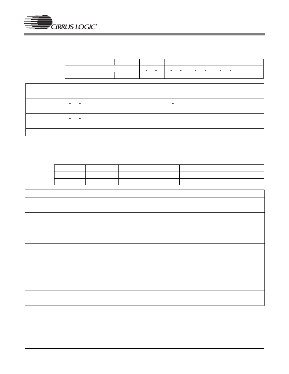
Control Register 3
Address
0
×
03
CONTROL_3
Read/Write
Default Value = 00h
Control Register 4
Address
0
×
04
CONTROL_4
Read/Write
Default Value = 3Fh
NOTE: 1. The FIELD pin (pin 9) remains an output pin in SLAVE mode. However, the FIELD pin state does not
toggle in SLAVE mode and its output state should be considered random.
Bit Number
7
6
5
4
3
2
1
0
Bit Name
RESERVED
FD THR C1 FD THR C2 FD THR SV FD THR EN
CBAR
Default
0
0
0
0
0
0
0
0
Bit
Mnemonic
Function
7:5
-
reserved
4
FD THR C1
feedthrough enabled for composite 1 output (0 = off, 1 = on)
3
FD THR C2
feedthrough enabled for composite 2 output (0 = off, 1 = on)
2
FD THR SV
feedthrough enabled for s-video (on luma signal) (0 = off, 1 = on)
1
FD THR_EN
Enable (1 = enable) input to feed through during inactive lines
0
CBAR
internal color bar generator (0 = off, 1 = on)
Bit Number
7
6
5
4
3
2
1
0
Bit Name
CB_H_SEL
CB_FLD_SEL
(1)
COMDAC_PD SVIDLUM_PD SVIDCHR_PD
R_PD
G_PD
B_PD
Default
0
0
1
1
1
1
1
1
Bit
Mnemonic
Function
7
CB_H_SEL
Composite Blank / HSYNC output select (1 = CB select, 0 = HSYNC select)
6
CB_FLD_SEL
Composite Blank / FIELD output select (1 = CB select, 0 = FIELD select)
(1)
5
COMDAC_PD
power down composite DAC
0: power up, 1: power down
4
SVIDLUM_PD
power down luma s-video DAC
0: power up, 1: power down
3
SVIDCHR_PD
power down chroma s-video DAC
0: power up, 1: power down
2
R_PD
power down red rgb video DAC
0: power up, 1: power down
1
G_PD
power down green rgb video DAC
0: power up, 1: power down
0
B_PD
power down blue rgb video DAC
0: power up, 1: power down