2 register description, 1 control registers, Register description – Cirrus Logic CS4955 User Manual
Page 36
CS4954 CS4955
36
DS278F6
8.2
Register Description
A set of internal registers are available for control-
ling the operation of the CS4954/5. The registers
extend from internal address 0×00 through 0×5A.
Table
shows a complete list of these registers and
their internal addresses. Note that this table and the
subsequent register description section describe the
full register map for the CS4954 only. A complete
CS4955 register set description is available only to
Macrovision
TM
ACP-PPV Licensed Buyers.
8.2.1 Control Registers
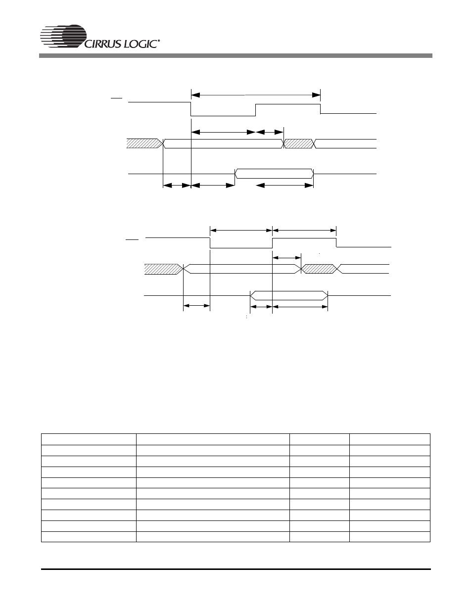
PADR
RD
PDAT[7:0]
T
rd
T
rpw
T
rah
T
rda
T
rdh
T
as
Figure 28. 8-bit Parallel Host Port Timing: Address Read Cycle
WR
PADR
PDAT[7:0]
T
as
T
wds
T
wdh
T
wpw
T
wr
T
wac
Figure 29. 8-bit Parallel Host Port Timing: Address Write Cycle
Address
Register Name
Type
Default value
0
×
00
control_0
r/w
01h
0
×
01
control_1
r/w
02h
0
×
02
control_2
r/w
00h
0
×
03
control_3
r/w
00h
0
×
04
control_4
r/w
3Fh
0
×
05
control_5
r/w
00h
0
×
06
control_6
r/w
00h
0
×
07
RESERVED
0
×
08
bkg_color
r/w
03h
Table 9. Control Registers