Cirrus Logic CS1631 User Manual
Page 37
CS1630/31
DS954F3
37
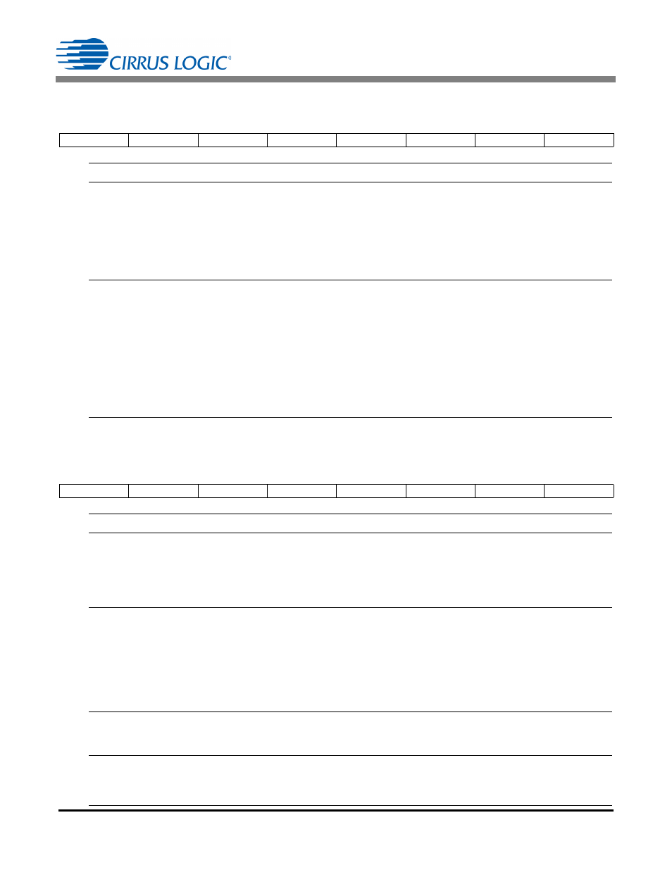
6.20 Configuration 15 (Config15)
–
Address 47
6.21 Configuration 16 (Config16)
–
Address 48
7
6
5
4
3
2
1
0
EXIT_PH3
EXIT_PH2
EXIT_PH1
EXIT_PH0
DECL_PH3
DECL_PH2
DECL_PH1
DECL_PH0
Number
Name
Description
[7:4]
EXIT_PH[3:0]
Configures the number of channel 1 switching periods between phase syn-
chronization conditions on the second stage. EXIT_PH[3:0] provides a hyster-
esis to prevent consecutive resynchronizations by the controller. The value is
an unsigned integer in the range of 0
value15. EXIT_PH[3:0] needs to be
configured only for designs that use a dual channel synchronization circuit and
is not directly driven from the SYNC pin. The RESYNC bit must be enabled
(see “Configuration 17 (Config17) – Address 49” on page 38).
[3:0]
DECL_PH[3:0]
Configures the number of second stage switching periods with improper out-
put identification until the controller resynchronizes. There is a counter that
increments by 1 on improper output identification and decrements by 2 if
proper output identification is measured. If this counter exceeds the threshold
set by bits DECL_PH[3:0] and the controller has not seen a phase resynchro-
nization in EXIT_PH[3:0] cycles, the controller resynchronizes. The value is an
unsigned integer in the range of 0
value15. DECL_PH[3:0] needs to be con-
figured only for designs that use a dual channel synchronization circuit and is
not directly driven from the SYNC pin. The RESYNC bit must be enabled (see
“Configuration 17 (Config17) – Address 49” on page 38).
7
6
5
4
3
2
1
0
RE2_ZCD2
RE2_ZCD1
RE2_ZCD0
CH2_ZCD2
CH2_ZCD1
CH2_ZCD0
SCP
VDIFF
Number
Name
Description
[7:5]
RE2_ZCD[2:0]
Sets the fixed time delay T
RE2ZCD(delay)
for zero-current detection (ZCD) com-
parator to account for the delay on the rising edge of ZCD for channel 2. The
value is an unsigned integer in the range of 0
value7. The delay is defined
by:
[4:2]
CH2_ZCD[2:0]
Sets fixed time delay T
CH2ZCD(delay)
to account for the delay of the second
stage zero-current detection (ZCD) comparator during channel 2 switching
cycles when the voltage applied to the FBAUX pin falls below the 200mV ZCD
comparator threshold. Configuring T
CH2ZCD(delay)
is essential to achieve good
quasi-resonant (valley switching) performance. The value is an unsigned inte-
ger in the range of 0
value7. The delay is defined by:
[1]
SCP
Configures the second stage short circuit protection.
0 = Enable short circuit protection
1 = Disable short circuit protection
[0]
VDIFF
Configures the V
Diff
fault mechanism for use by the protection module.
0 = Enable V
Diff
fault
1 = Disable V
Diff
fault
T
RE2ZCD delay
RE2_ZCD
=
[2:0] 50ns
T
CH2ZCD delay
CH2_ZCD
=
[2:0] 50ns