1 series & parallel two-channel output, Figure 17. tapped buck parallel output model, Figure 18. flyback series output model – Cirrus Logic CS1631 User Manual
Page 17: Figure 19. buck series output model
CS1630/31
DS954F3
17
The buck stage is controlled by measuring current in the buck
inductor and voltage on the auxiliary winding. Quasi-resonant
operation is achieved by detecting buck inductor
demagnetization using an auxiliary winding. The digital control
algorithm rejects line-frequency ripple created on the second
stage input by the front-end boost stage, resulting in the
highest possible LED efficiency and long LED life.
The tapped buck stage operates similar to a buck stage. The
tapped buck topology provides minimum turn-on time and
improves conversion efficiency when large input-to-output
voltage ratio is present. The tapped buck inductor behaves as
a transformer for voltage conversion and is controlled by
measuring current in the tapped inductor and voltage on the
auxiliary winding. Quasi-resonant operation is achieved by
detecting tapped inductor demagnetization using an auxiliary
winding.
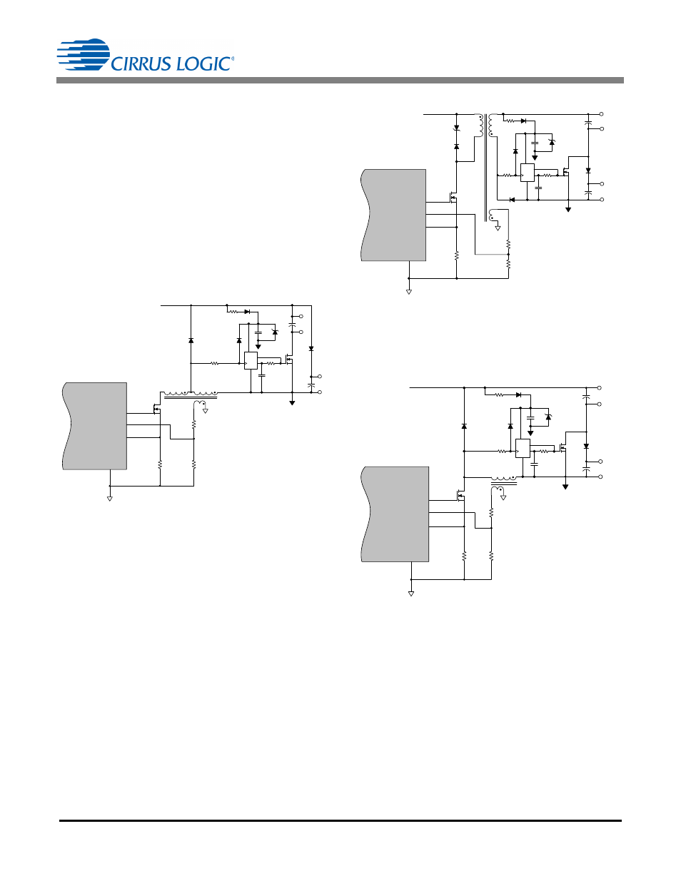
5.8.1 Series & Parallel Two-Channel Output
The CS1630/31 is designed to be programmed to support
series or parallel two-channel output configurations using one
set of power magnetics. Series or parallel configuration is set
by bit STRING and bit LED_ARG in the Config3 register (see
"Configuration 3 (Config3) – Address 35" on page 32). A
parallel connection for a flyback stage and buck stage are
connected differently: an NMOS switch is used in flyback
configuration, and a PMOS switch is used in buck/tapped
buck configuration (see Figures 15, 16, and 17).
Similarly, a series connection in a flyback stage and buck
stage use an NMOS switch and a PMOS switch, respectively,
as shown in Figures 18 and 19.
R13
R11
R14
Q4
L3
CS1630 /31
FBAUX
GND
13
GD
FBSENSE
15
12
11
D8
V
B S T
R12
D9
C9
C11
C12
D11
R15 D10
Q5
R16
C10
Z3
IGND
LED2+
LED1+
LED1-
LED 2-
D
GND
_
Q
V CC
Figure 17. Tapped Buck Parallel Output Model
D7
R13
Z2
R11
R14
Q4
CS1630 /31
FBAUX
GND
13
GD
FBSENSE
15
12
11
T1
V
B S T
R12
D9
C9
D8
R15 D10
R16
C10
Z3
D
GND
_
Q
V CC
Q5
IGND
C12
LED 2+
LED2-
C11
LED 1+
LED 1-
D11
Figure 18. Flyback Series Output Model
R13
R11
R14
Q4
L3
CS1630 /31
FBAUX
GND
13
GD
FBSENSE
15
12
11
V
B S T
R12
D9
C9
R15
D10
R16
C10
Z3
D
GND
_
Q
V CC
Q5
IGND
D11
D8
C12
LED1+
LED1-
C11
LED2+
LED 2-
Figure 19. Buck Series Output Model