1 power line calibration specification, 10 power line calibration – Cirrus Logic CS1631 User Manual
Page 21
CS1630/31
DS954F3
21
Beyond this temperature, the IC shuts down using the
mechanism discussed above.
If the external overtemperature protection and the
temperature compensation for CCT control features are not
required, connect the eOTP pin to GND using a 50k
to
500k
resistor to disable the eOTP feature so that the
programmed temperatures Temp
Wakeup
and Temp
Shutdown
codes are greater than the measured 8-bit code
corresponding to the total resistance on pin eOTP.
5.10 Power Line Calibration
The CS1630/31 integrates power line calibration technology
within the controller to enable calibration and end-of-line
programming without the need for an additional electrical
connection, as shown in Figure 23.
The power line calibration uses a phase-cut mechanism for
data generation and return-to-zero data encoding to eliminate
the need for clock synchronization. A code /command can be
created by using the combination of input phase angles, as
detailed in "Power Line Calibration Characteristics" on page 9.
When an initial program mode command has been detected,
the controller will begin to enter calibration mode. After key
parameters of the lighting system have been characterized
and programmed, a burn-in code plus an end-program mode
command is transmitted, instructing the controller to exit the
calibration mode. Power line calibration and end-of-line
programming requires no human intervention. The
CS1630/31 provides registers that allow up to three attempts
for LED output current trimming over power line calibration.
Six registers store the three optional color control system
calibration values for channel 1 color calibration and channel
2 color calibration. For more detail regarding color calibration,
see "Channel 1 Color Calibration 3A (CH1_CAL3A) – Address
119" on page 51 through "Channel 2 Color Calibration 3C
(CH2_CAL3C) – Address 126" on page 53.
5.10.1 Power Line Calibration Specification
To ensure the success of phase detection, the angle for each
bit is specified as shown in "Power Line Calibration
Characteristics" on page 9. The CS1630/31 power line
calibration system operates under universal line voltage and
frequency with a leading-edge, phase-cut waveform.
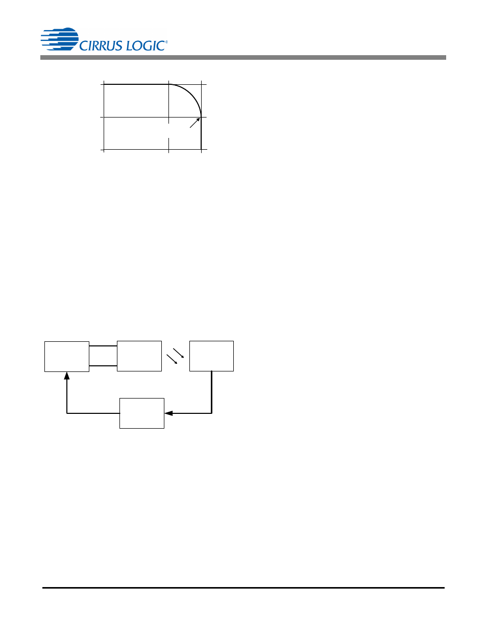
Temperature (°C)
Cu
rr
e
n
t
(I
LE
D
, N
o
m
.)
125
95
50%
100%
0
25
eOTP Trips and
Shuts Off Lamp
Figure 22. LED Current vs. eOTP Temperature
Power Supply
LED Lamp
with
CS1630/31
Photodetector
Light
Measurement
Light
Calibrator
Line
Neutral
Figure 23. Power Line Calibration Block Diagram