1 clamp overpower protection, Quasi-resonant second stage, 8 quasi-resonant second stage – Cirrus Logic CS1631 User Manual
Page 16: Figure 14. clamp pin model, Figure 15. flyback parallel output model, Figure 16. buck parallel output model, Clamp
CS1630/31
16
DS954F3
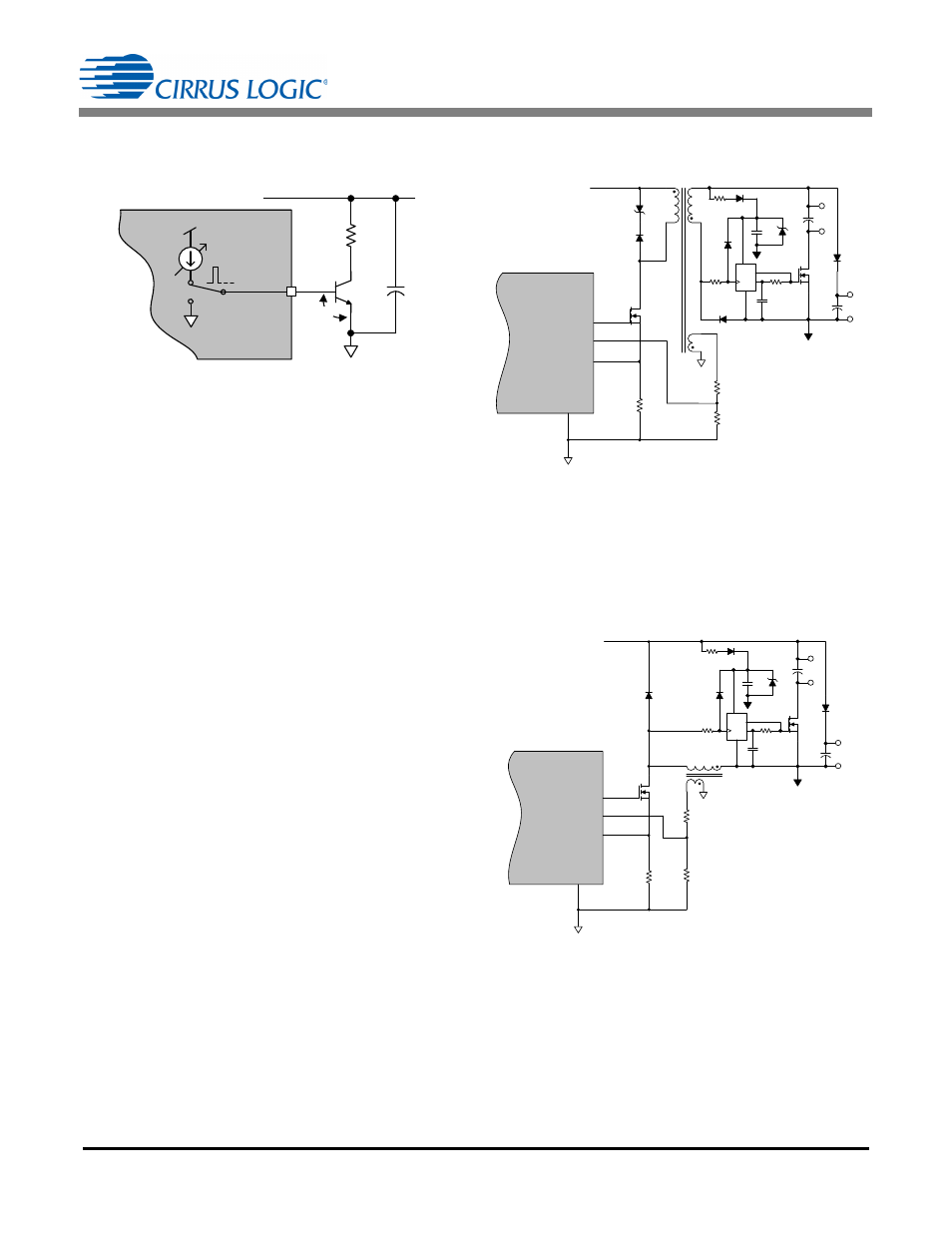
The CS1630/31 provides active clamp circuitry on the CLAMP
pin, as shown in Figure 14.
A PWM control loop ensures that the boost output
voltage V
BST
does not exceed 227V for 120VAC applications
or 424V for 230VAC applications. This control turns on the
BJT of the voltage clamp circuit, allowing the clamp circuit to
sink current through the load resistor, preventing boost output
voltage V
BST
from exceeding the maximum safe voltage.
5.7.1 Clamp Overpower Protection
The CS1630/31 clamp overpower protection (COP) control
logic continuously monitors the turn-on time of the clamp
circuit. If the cumulative turn-on time exceeds 84.48ms during
the internally generated 1 second window time, a COP event
is actuated, disabling the boost and second stages. The clamp
circuitry is turned off during the fault event.
5.8 Quasi-resonant Second Stage
The second stage is a quasi-resonant current-regulated DC-
DC converter capable of flyback, buck, or tapped buck
operation. The second stage output configuration is set by bit
S2CONFIG in register Config12 (see "Configuration 12
(Config12) – Address 44" on page 36) and bits BUCK[3:0] in
register Config10 (see "Configuration 10 (Config10) – Address
42" on page 35). To deliver the highest possible efficiency, the
second stage can operate in quasi-resonant mode and
provides constant output current with minimum line-frequency
ripple. Primary-side control is used to simplify system design
and reduce system cost and complexity.
The digital algorithm ensures monotonic dimming from 0% to
100% of the dimming range with a linear relationship between
the dimming signal and the LED current.
Figure 15 illustrates a quasi-resonant flyback stage
configured for two-channel parallel output.
The flyback stage is controlled by measuring current in the
transformer primary and voltage on the auxiliary winding.
Quasi-resonant operation is achieved by detecting
transformer flyback using an auxiliary winding.
A quasi-resonant buck stage configured for two-channel
parallel output is illustrated in Figure 16.
CLAMP
Q3
R10
I
CLA MP
V
B S T
S1
CS1630 /31
V
B E
VDD
3
C8
Figure 14. CLAMP Pin Model
D7
R13
Z2
R11
R14
Q4
CS1630 /31
FBAUX
GND
13
GD
FBSENSE
15
12
11
T1
V
B S T
R12
D9
C9
C11
C12
D11
D8
R15 D10
Q5
R16
C10
Z3
IGND
LED2+
LED 1+
LED 1-
LED2-
D
GND
_
Q
V CC
Figure 15. Flyback Parallel Output Model
R13
R11
R14
Q4
L3
D8
CS1630 /31
FBAUX
GND
13
GD
FBSENSE
15
12
11
V
B S T
R12
D9
C9
C11
C12
D11
R15 D10
Q5
R16
C10
Z3
IGND
LED 2+
LED1+
LED 1-
LED 2-
D
GND
_
Q
V CC
Figure 16. Buck Parallel Output Model