2 plc program mode characters, 3 calibration mode operation code, Table 1. power line calibration characters – Cirrus Logic CS1631 User Manual
Page 22: Table 2. power line calibration operation code
CS1630/31
22
DS954F3
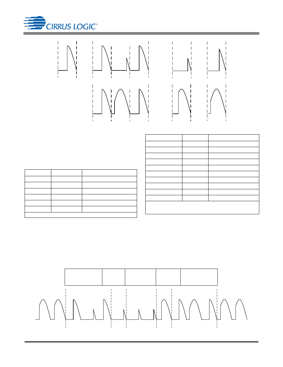
5.10.2 PLC Program Mode Characters
In order to program the CS1630/31, a set of encoded
characters is built from specific phase-cut waveform patterns.
Figure 24 illustrates the phase-cut waveform encoding
recognized by the CS1630/31 power line calibration system.
As shown in Table 1, six characters are formed using the
special character and two-bit encoded data.
5.10.3 Calibration Mode Operation Code
The CS1630/31 power line calibration system requires a start
and stop operation code to activate and deactivate power line
calibration mode. Once in the power line calibration mode,
operation codes (OPCODE) will be used to program specific
addresses using the OPCODE listed in Table 2.
The LED light flashes seven times to indicate a command
error. The LED flashes two times when OTP registers are
programmed successfully and four times when programming
is unsuccessful. Figure 25 illustrates an example of a power
line calibration mode command sequence and the cut-
waveform pattern.
Character
Code
Notes
Start Char
(SC)00(SC)
PLC Program Start Character
(1)
Stop Char
(SC)11(SC)
PLC Program Stop Character
Duo-bit ‘00’
00
2-bit Data [00]
Duo-bit ‘01’
01
2-bit Data [01]
Duo-bit ‘10’
10
2-bit Data [10]
Duo bit ‘11’
11
2-bit Data [11]
Note: (1) A Special Character (SC) must precede and follow the Duo-bit.
Table 1. Power Line Calibration Characters
90°
Special Char
‘11’
146°
‘01’
62°
‘10’
118°
‘00’
34°
90°
146°
90°
PLC Stop Char
90°
34°
90°
PLC Start Char
Figure 24. Power Line Calibration Mode Character Waveforms
PLC Start Character
Addr Bcast
&
Simple Code
00
PLC Operation Code
(4-bit)
0000
Odd Parity
&
Don’t Care
10
PLC Stop Character
Before Transmit
After Transmit
135°
135°
135°
135°
90°
34°
90°
90°
146°
90°
34°
34°
118°
34°
Figure 25. Power Line Calibration Mode Example
Calibration Command Sequence
Start Char [(SC)00(SC)]
Addr Bcast
&
Simple Code
[1 Duo-bit]
OPCODE
[2 Duo-bits]
Odd Parity
&
Don’t Care
[1 Duo-bit]
Stop Char [(SC)11(SC)]
Name
OPCODE
Description
NOP
0000
No Operation
INIT_PROG_MODE
0001
Initialize program mode
I2C_WRITE
0010
Perform a generic I
2
C write
0011
Reserved
BURN_OTP
0100
Initiate an OTP write cycle
STR1_OFFSET
0101
Write String 1 offset
STR2_OFFSET
0110
Write String 2 offset
WRITE_CRC
0111
Write CRC value
END_PROG_MODE
1000
Disable programming mode
WRITE_DIM
1001
Sets PLC dim value
Notes: (1) Allows other commands to program the device under test.
(2) Range of Offset tolerance is ±15%.
(3) The light is flashed to indicate pass or fail.
Table 2. Power Line Calibration Operation Code