WIKA 732.15.100 User Manual
Page 8
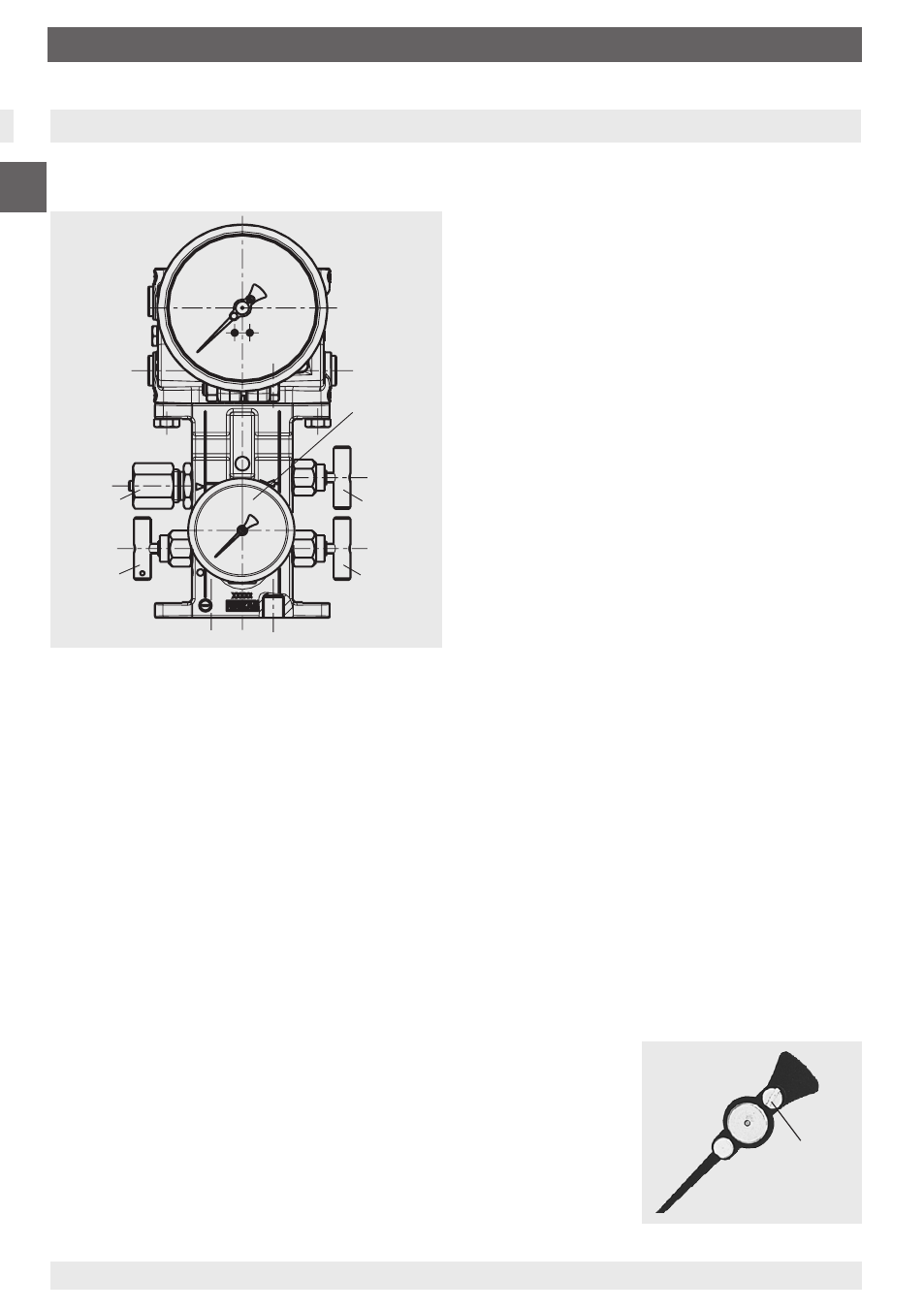
5. Valve manifold with working pressure gauge (optional)
Slotted
screw
8
Test connection
M20 x 1.5
Isolating valve
i
Working
pressure gauge
NS 63
Pressure
equalising
valve
Isolating valve
j
11592011.04 06/2014 GB/D/F/I
GB
11592649.01AB
WIKA operating instructions differential pressure gauge models 712.15.100, 732.15.100
5. Valve manifold with working pressure gauge (optional)
The compact optional flanged valve manifold for an NG 63 working pressure gauge allows the
central measurement of level and working pressure in a single device.
To isolate line pressures without inter-
rupting the process, enabling gauge
removal/examination and protecting the
gauge against overpressure of n-times
rated pressure which may occur during
plant pressure testing.
To protect the gauge against pressure
surges/pressure spikes, and thus against
unspecified operating conditions
For gauge shut-downs, if no measure-
ments are required for long operating
periods, i.e. if only occasional measure-
ments are necessary (to increase service
life of those differential and working pressu-
re gauges with a high frequency of pressure
fluctuations).
Recalibration of differential pressure
gauges (tank volume display)
a) Close the plus and minus shut-off valve
b) Afterwards open the pressure equalising
valve, wait for a short period of time and then
close the pressure equalising valve again.
c) Connect the pressure standard and test pump using the additional G ¼ female port in the
plus chamber of the measuring system
d) Remove the test connection screw from the minus side valve manifold
e) The plus side can then be pressurised
f) After adjustment:
- Close the air bleed screw
- Disconnect the pressure standard and test pump and close the connection
- Slowly open first the plus and then the minus shut-off valve
Test connection M20 x 1.5 for checking the working pressure gauge
The pressure equalising valve allows a zero point control during operation (with open valve).
a)
Close the plus and minus shut-off valve
b) Afterwards open the pressure equalising valve
While the media is flowing from the higher pressure side to the other side, the differential
pressure at the pressure gauge drops to zero (the differential pressure display must be at
zero, i.e. within the zero tolerance range which shows that the gauge is working correctly).
A zero adjustment can be made using the standard integra-
ted, adjustable pointer (remove snap fit bezel incl. window and
sealing ring beforehand). Twisting the slotted screw on the
adjustable pointer you can adjust the zero point.
After completing the zero adjustment, the snap fit bezel,
incl. window and ‚o‘-ring seal, must be correctly re-fitted
and the pressure equalising valve must then be closed again.
Subsequently the zero point of versions with integrated
transmitter (see page 9) should be checked.
c) Close the pressure equalising valve
d) Slowly open first the plus and then the minus shut-off valve
5. Ventilblock mit Betriebsdruckanzeige (Option)
Der optional anflanschbare kompakte Ventilblock mit Betriebsdruck-Messgerät NG 63
ermöglicht die zentrale Messung von Füllstand und Betriebsdruck in einem Gerät.
Absperrung der Messleitungsdrücke ohne
Störung des Betriebsablaufes
- zur Gerätedemontage/-prüfung
- zum Schutz des Gerätes gegen unzu-
lässige Überdruckbelastung bei n-facher
Prüfdruckbelastung von Anlagen
Schutz des Gerätes gegen Druckstöße/
-schläge und damit undefinierten
Betriebsverhältnissen
Gerätestilllegung, wenn über längere Be-
triebszeiten keine Messung erforderlich,
d.h. nur sporadische Messungen (zur
Erhöhung der Lebensdauer von Differenz-
und Betriebsdruck-Messgeräten mit hoher
Frequenz der Druckwechsel)
Rekalibrierung des Differenzdruckmess-
gerätes (Tankinhaltsanzeige)
a) Plus- und Minusabsperrhahn schließen
b)
Danach
Druckausgleichsventil öffnen,
kurz abwarten
und anschließend Druckaus-
gleichsventil wieder verschließen
c) Über zusätzliches G ¼ Innengewinde in der Pluskammer des Messsystems wird
Drucknormal und Druckerzeuger angeschlossen
d) Im Ventilblock auf der Minusseite Prüfanschluss-Schraube entfernen
e) Plusseite kann jetzt mit Druck beaufschlagt werden
f) Nach erfolgter Justage:
- Prüfanschlussschraube wieder schließen
- Drucknormal und Druckerzeuger wieder entfernen und Anschluss verschließen
- zuerst Plus-, dann Minusabsperrhahn langsam öffnen
Prüfanschluss M20 x 1,5 für die Überprüfung des Betriebsdruck-Messgerätes
Mit dem Druckausgleichsventil wird eine Nullpunktkontrolle im laufenden Betriebsprozess
(bei geöffnetem Ventil) ermöglicht.
a)
Plus- und Minusabsperrhahn schließen
b) Danach
Druckausgleichsventil öffnen
Der Messstoff strömt von der Seite höheren Druckes nach der Gegenseite, Differenz-druck
am Messgerät fällt auf Null (Differenzdruckanzeige muss auf Null, d.h. in den Bereich des
Nullpunkt-Toleranzbandes gehen, Gerätefunktion ist damit in Ordnung).
Bei Abweichung kann eine Nullpunktkorrektur über den
standardmäßig eingebauten Verstellzeiger erfolgen (vorher die
Spannbügel lösen und Sichtscheibe und Dichtung entfernen).
Die Nullpunkt-Verstellung wird durch Verdrehen der Schlitz-
schraube am Verstellzeiger erreicht. Nach erfolgter Nullpunkt-
korrektur Schnappring incl. Sichtscheibe und Dichtung
wieder befestigen und Druckausgleichsventil schließen.
Anschließend ist bei Ausführungen mit integriertem Transmitter
auch dessen Nullpunkt zu kontrollieren (siehe Seite 27).
c)
Druckausgleichsventil wieder verschließen
d) zuerst Plus-, dann Minusabsperrhahn langsam öffnen