Installation – WIKA 732.15.100 User Manual
Page 5
11592649.01
Pressure
connections G 1/4
Mounting holes M8
Isolating
valve
i
Test
connection
11592011.04 06/2014 GB/D/F/I
GB
WIKA operating instructions differential pressure gauge models 712.15.100, 732.15.100
5
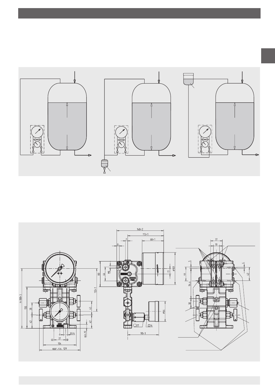
Types of installation for level measurement
Standard in cryogenic equipment 2 examples with condensate formation
(liquid gases)
3. Installation
Filling
hole
Filling
hole
Filling hole
p
D
Condensate
⇔
p
D
p
D
Constant
level
vessel
h
h
h
Δp
Δp
Δp
p
D
p
B
p
D
p
B
Drain pipe
Drain pipe
Condensate
Drain pipe
i
j
i
j
i
j
Wall mounting
Installation/fastening to the 4 mounting holes M8 / 2 fixing holes Ø 8.5
Pressure
equalising valve
Pressure connections G 1/4
Ø 8.5 fixing holes
Isolating valve
j
This manual is related to the following products: