Transmitter for working pressure indication – WIKA 732.15.100 User Manual
Page 13
Specifications
A-10
IS-20
Data sheet
PE 81.60
PE 81.50
Design
standard
intrinsically safe
Pressure ranges
bar
0 ... 6 to 0 ... 60
0 ... 6 to 0 ... 60
Outputs
mA
4 ... 20
4 ... 20 (line transformer)
Medium temperature
°C
-30 ... +100
-20 ... +80
Ambient temperature
°C
-30 ... +100
-20 ... +80
Wetted parts
stainless steel
stainless steel
Power supply U
B
DC
8 V < U
B
≤ 30 V
10 V < U
B
≤ 30 V
Maximum load R
A
Ohm
R
A
≤ (U
B
- 8 V) / 0.02 A R
A
≤ (U
B
- 10 V) / 0.02 A
Accuracy
BFSL
% of span
≤ 0.5
≤ 0.25
Compensated temperature
range
°C
0 ... +80 °C
0 ... +80 °C
Wiring details,
2-wire
11592011.04 06/2014 GB/D/F/I
GB
WIKA operating instructions differential pressure gauge models 712.15.100, 732.15.100
13
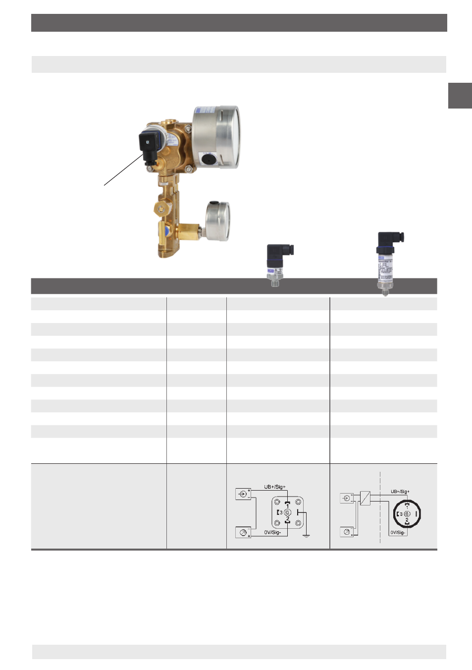
9. Transmitter for working pressure indication
9. Transmitter for working pressure indication (optional)
Standard version model A-10
or Ex version model IS-20
Transmitter for working
pressure indication
The corresponding operating instructions are included in the delivery
of each differential pressure gauge with integrated transmitter for
working pressure indication.
Non hazardous
area
Hazardous
(classified) area
The transmitters for the working pressure
are screwed in sideways, on the left side of
the minus measurement chamber and can,
if necessary, be retrofitted on-site.
Pressure connection for Transmitter:
G 1/4 (male)