WIKA 732.15.100 User Manual
Page 7
11592011.04 06/2014 GB/D/F/I
GB
WIKA operating instructions differential pressure gauge models 712.15.100, 732.15.100
7
11557711.01AB
Mounting holes
M8
G 1/4 pressure connections
G 1/4 pressure connections
Additional pressure connections
Three additional G ¼ female threads are
available on the minus measurement
chamber (the right measuring cell flange
when viewed from the back) e.g. for
connecting a pressure switch, safety
valve or A-10 Cryo or IS-20 transmitters
Two G ¼ female threads are available on
the plus measurement chamber (the left
cell flange when viewed from the back)
e.g. for recalibration
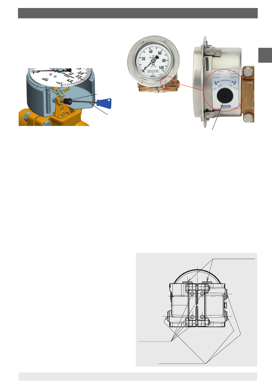
Turn clockwise:
reduce measuring range
Turn anticlockwise: expand measuring range
Adjustable measuring span
Adjustable measuring
span
Allen key
(included in delivery)
Cover cap for adjustable
measuring span
1. The span adjustment, situated at the ‚4 o‘clock‘ point on the instrument case, is accessible
through the case by removing the cover cap.
2. Charge the instrument to the desired nominal pressure.
3. To set the pointer to the span value, using an allen key (size 3 mm) inserted into the
funnel, turn it either clockwise (reduce the measuring range) or anticlockwise (expand the
measuring range). The gauge will then be fully adjusted to the required measuring range.
4. If the gauge is equipped with a transmitter model 89x.44 (see page 9), then this procedure
will also adjust the output signal to the new measuring range.
5. After completing the adjustment the equipment should be resealed with the cover cap.