Operating the vs-169tp 16x9 cat 5 matrix switcher – Kramer Electronics VS-169TP User Manual
Page 27
Operating the VS-169TP 16x9 CAT 5 Matrix Switcher
23
23
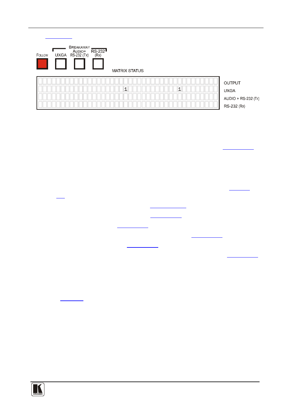
shows the MATRIX STATUS display in the Follow Mode:
0
0
0
0
0
L
L
0
0
0
1
1
1
0
1
1
3
4
7
8
-
6
5
2
0
0
0
3
0
0
0
Figure 12: MATRIX STATUS Display in the Follow Mode
In the breakaway mode, you can select the output port from which the reply
will be returned, by pressing the RS-232 (Rx) front panel button in the
BREAKAWAY area, and then selecting the desired output (see
Section 9.7
9 Operating the VS-169TP 16x9 CAT 5 Matrix Switcher
).
This section describes how to:
•
Toggle inputs #1 and #2 between local and remote inputs (see
Section
•
Read the 7-segment displays (see
Section 9.3.1
•
Use the IN and OUT buttons (see
Section 9.3
•
Confirm settings (see
Section 9.4
•
Store and recall input/output configurations (see
Section 9.5
•
Lock the front panel (see
Section 9.6
•
Choose the audio-follow-video or the breakaway feature (see
Section 9.7
9.1
Switching Inputs #1 and #2 between local and remote
You can select the function of the IN 1 and IN2 front panel buttons to be either
local or remote (TP), via the four rear panel SELECT pushbuttons (items 18 and
).
The UXGA SELECT buttons define the VIDEO signal and the AUDIO/RS-232
SELECT buttons define the AUDIO and RS-232 signals. All four buttons switch
independently.
This setting can only be changed via these rear panel buttons and cannot be
changed from the front panel or any other interface command.