Figure 10: switching an input to an output, Figure 11: switching an input to several outputs – Kramer Electronics VS-169TP User Manual
Page 26
KRAMER: SIMPLE CREATIVE TECHNOLOGY
Understanding the VS-169TP 16x9 CAT 5 Matrix Switcher
22
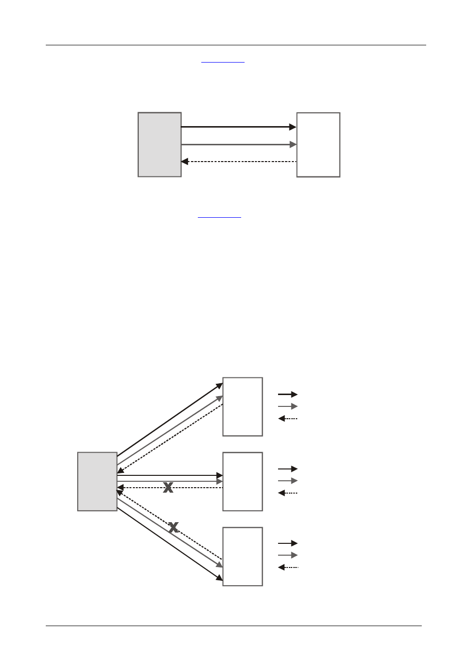
, when the transmitter (video, audio and
RS-232 signals) connected to IN 10 is switched to OUT 5, all three signals
are passed to the receiver connected to OUT 5, and the RS-232 reply
command returns from the receiver (OUT 5) back to the transmitter (IN 10).
IN 10
OUT 5
UXGA
AUDIO + RS-232 (Tx)
RS-232 (Rx)
Figure 10: Switching an Input to an Output
In the example illustrated in
, the transmitter (video, audio and
RS-232 signals) connected to IN 10 is switched to OUT 3, OUT 5 and OUT 8 –
each of which is connected to a receiver. The signals are passed to all the
outputs and the RS-232 signal generates a reply command on each receiver.
The reply signal on each receiver contains not only different information, but
can be sent at different times and in different formats. When this information is
passed back to IN 10, it might be rejected by the control unit since it includes a
mix of reply signals, and control of the destination units becomes impossible.
To avoid a mixed RS-232 reply command, the VS-169TP passes only one
reply from the output back to the input. In the FOLLOW mode, the
VS-169TP passes the RS-232 reply from the output which has the lowest
numerical value (in this example, OUT 3). Other RS-232 replies are blocked.
IN 10
OUT 3
Blocked
Blocked
OUT 5
OUT 8
UXGA
AUDIO + RS-232 (Tx)
RS-232 (Rx)
UXGA
AUDIO + RS-232 (Tx)
RS-232 (Rx)
UXGA
AUDIO + RS-232 (Tx)
RS-232 (Rx)
Figure 11: Switching an Input to Several Outputs