Table 1 – Kramer Electronics VS-169TP User Manual
Page 11
Your VS-169TP 16x9 CAT 5 Matrix Switcher
7
7
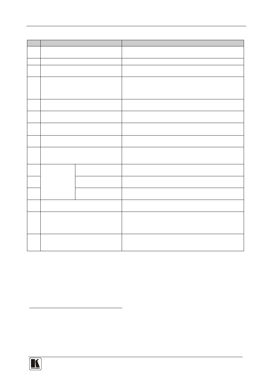
Table 1: VS-169TP 16x9 CAT 5 Matrix Switcher Front Panel Functions
#
Feature
Function
1
IR Receiver/IR LED
The red LED is illuminated when receiving signals from the
infrared remote control transmitter
2
POWER LED
Illuminates green when receiving power
3
ALL Button
Pressing ALL followed by an IN button, connects that input to
all outputs
4
OFF Button
Press an OUT selector button and then an OFF button to
disconnect that output from the inputs
Press the ALL button and then the OFF button to disconnect
all the outputs
5
IN Buttons (1 to 16)
Select the input (including the two local built-in
transmitters) to switch to the output
6
OUT Buttons (1 to 8, LOCAL)
Select the output to which the input is switched, including
the local built-in receiver
7
STO Button
Pressing STO followed by an IN button (from 1 to 15)
stores the current setting
8
in the non-volatile memory
RCL Button
Pressing RCL followed by an IN button (from 1 to 15)
recalls a setup from the non-volatile memory
9
FOLLOW Button
Pressing FOLLOW followed by the TAKE button enters the
Follow mode in which the UXGA, audio and RS-232
signals switch simultaneously
10
BREAKAWAY
UXGA Button
When pressed twice
11
the button illuminates and the actions
that follow will relate to UXGA
AUDIO+RS-232 (Tx)
Button
When pressed twice
the button illuminates and the actions
that follow will relate to audio/direct
12
RS-232
RS-232 (Rx) Button When pressed twice
the button illuminates and the actions
that follow will relate to RS-232 reply
13
MATRIX STATUS 40x4 LCD Display
Displays the selected INPUT (video, audio and RS-232)
switched to the OUTPUT
14
TAKE Button
Pressing TAKE toggles the mode between the Confirm
mode
15
and the At Once mode (user confirmation per action
is unnecessary). When in Confirm mode, pressing the
TAKE button will implement a pending configuration
LOCK Button
Toggles activation/inactivation of the front panel buttons.
When the front panel is locked you can still control via the
interfaces
1 For example, press ALL and then IN button # 3 to connect input # 3 to all the outputs
2 For example, press STO and then the IN button # 3 to store in Setup # 3
3 After pressing once, the button blinks
4 Direct RS-232 refers to the signal transmitted from the transmitter to the receiver; RS-232 reply refers to the signal returned
from the receiver to the transmitter
5 When in the Confirm mode, the TAKE button illuminates