Table 2 – Kramer Electronics VS-169TP User Manual
Page 13
Your VS-169TP 16x9 CAT 5 Matrix Switcher
9
9
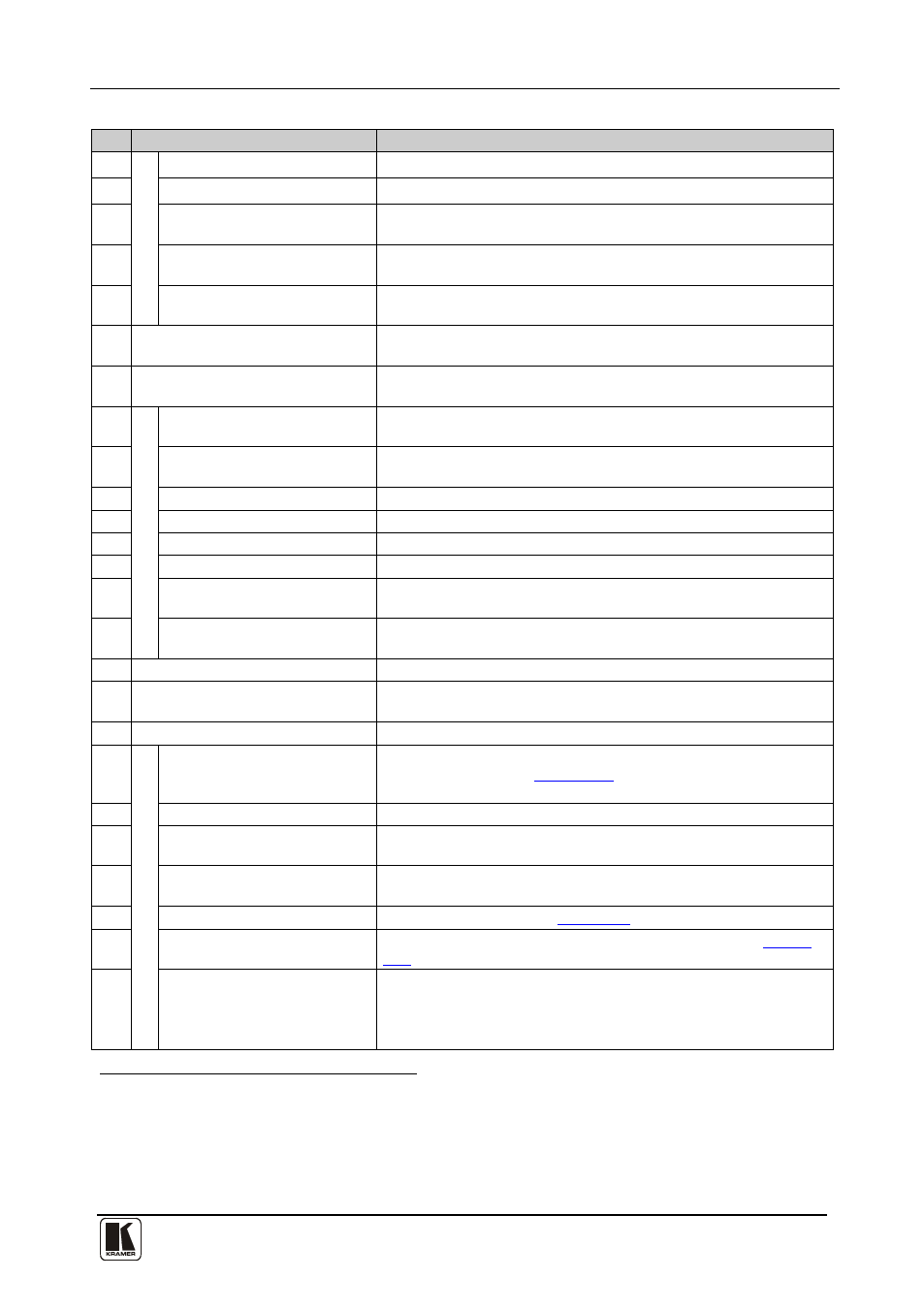
Table 2: VS-169TP 16x9 CAT 5 Matrix Switcher Rear Panel Functions
#
Feature
Function
16
LOC
A
L IN
P
U
TS
AUDIO IN 3.5mm Mini Jack
Connect to the local audio source (for local inputs 1 and 2)
17
UXGA IN 15-pin Connector
Connect to the UXGA source (for local inputs 1 and 2)
18
UXGA SELECT Pushbuttons Select the remote or LOCAL (built-in) receiver for input 1 and
input 2 for UXGA
19
AUDIO/RS-232 SELECT
Pushbuttons
Select the remote or LOCAL (built-in) receiver for input 1 and
input 2 for AUDIO and RS-232
20
RS-232 IN 9-pin D-sub
Connectors
Connect to the RS-232 source for local inputs 1 and 2
21 IN (1 to 16) RJ-45 Connectors
Connect to the LINE OUT RJ-45 connectors of the remote
transmitters via CAT 5
22 OUT (1 to 8) RJ-45 Connectors
Connect to the LINE IN RJ-45 connector of the remote receivers
via CAT 5
23
LO
C
A
L O
U
TP
U
TS
RS-232 OUT 9-pin D-sub
Connectors
Connect to the RS-232 local acceptor
24
EQ. Trimmer
Adjusts the cable compensation equalization level for the local
built-in receiver
25
LEVEL Trimmer
Adjusts the output signal level for the local built-in receiver
26
LINK LED
Illuminates when the local receiver receives the correct input signal
27
UXGA OUT 15-pin Connector Connects to the UXGA local acceptor
28
AUDIO OUT 3.5mm Mini Jack Connects to the analog audio local acceptor
29
HS Switch
Slide down
30
to set the H SYNC to negative polarity (-);
slide up to set the H SYNC to positive polarity (+)
VS Switch
Slide down
to set the V SYNC to negative polarity (+);
slide up to set the V SYNC to positive polarity (-)
31 POWER Switch
Switch for turning the unit ON and OFF
32 REMOTE IR 3.5mm Mini Jack
Connect to an external IR receiver unit for controlling the machine via
an IR remote controller (instead of using the front panel IR receiver)
33
POWER IN with fuse
AC connector enabling power supply to the
VS-169TP
34
C
ON
TR
OL
FLASH MAIN
Push in
to upgrade the switcher microcontroller to the latest
Kramer firmware (see
Section
), or release (the factory
default) for normal operation
35
RS-232 IN 9-pin D-sub Port
Connect to the PC or the remote controller
36
RS-232 OUT 9-pin D-sub Port Connects to the RS-232 IN 9-pin D-sub F port of the next unit in
the daisy-chain connection
37
RS-485 Terminal Block Port
Pins B (-) and A (+) are for RS-485; connect pin G to the cable
shield (if required)
38
SETUP DIP-switches
For setup of the unit (see
Section 6.2
39
ETH FLASH Pushbutton
Push in
to upgrade the ETH FLASH firmware version (see
Section
), or release (the factory default) for normal operation
40
ETHERNET Connector
Connects to the PC or other Serial Controller through computer
networking LAN
1 By default, both switches are set down (for a negative V SYNC and H SYNC polarity)
2 Covered by a cap. The 3.5mm connector at the end of the internal IR connection cable fits through this opening
3 Optional. Can be used instead of the front panel (built-in) IR receiver to remotely control the VS-169TP (only if the internal
IR connection cable has been installed)
4 Using a small screwdriver, if required