2 the status 7-segment display, 3 switching an input to an output, 1 switching one input to all outputs – Kramer Electronics VS-169TP User Manual
Page 28: The status 7-segment display, Switching an input to an output, Switching one input to all outputs, Figure 14: 7-segment display following power on
KRAMER: SIMPLE CREATIVE TECHNOLOGY
Operating the VS-169TP 16x9 CAT 5 Matrix Switcher
24
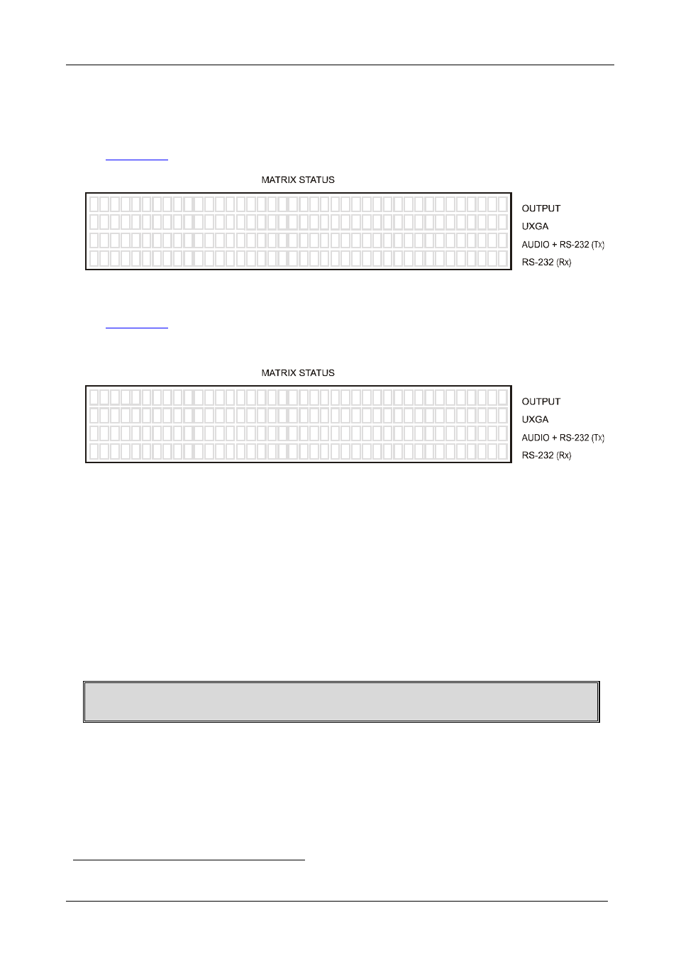
9.2 The STATUS 7-Segment Display
During normal operation, the STATUS display shows which inputs (UXGA,
AUDIO and/or RS-232) are switched to which outputs, as illustrated in
0
0
0
0
0
0
0
L
L
0
0
0
0
1
0
1
0
0
0
0
0
0
0
0
0
0
1
0
1
0
0
0
0
1
3
4
7
8
8
8
-
6
5
2
1
6
8
3
5
8
8
1
1
3
4
7
8
1
6
8
3
5
8
8
1
Figure 13: 7-segment Display During Normal Operation
shows an example of the display immediately after switching on
the power:
K R A M E R
U X G A
1 6 i n
8 + 1 o u t T w i s t e d P a i r s M A T R I X
S T E R E O A U D I O
F U L L D U P L E X R S - 2 3 2
-
-
-
E L E C T R O N I C S , L t d
V S - 1 6 9 T P / R e v 1 . 0
Figure 14: 7-segment Display Following Power ON
9.3 Switching an Input to an Output
To switch an input to an output:
1. Press the required OUT button from 1 to 8 or the L-L (local, on the
display).
The input under the selected output on the IN 7-segment display blinks.
2. Press an IN button to select the input to switch to the output.
The selected input number appears on the 7-segment display.
Incomplete operations on the
VS-169TP timeout after 25 seconds
9.3.1 Switching one Input to all Outputs
To switch one input to all the outputs (in the AT ONCE mode):
1. Press the ALL button.
The MATRIX STATUS display shows the three sets of digits
1 Each representing the present input number for that respective output
in the
follow mode blinking simultaneously. In the breakaway mode, only the