1 connecting the rs-232 ports, 1 connect the local rs-232 ports, 2 connect the control rs-232 ports – Kramer Electronics VS-169TP User Manual
Page 19: 2 setting the dip-switches, Connecting the rs-232 ports, Connect the local rs-232 ports, Connect the control rs-232 ports, Setting the dip-switches, Figure 5: dip-switch settings, Table 4: dip-switch settings
Connecting the VS-169TP 16x9 CAT 5 Matrix Switcher
15
15
6.1 Connecting the RS-232 Ports
The VS-169TP includes the following RS-232 ports:
•
Two local RS-232 IN ports and one local RS-232 OUT port (see
Section
•
RS-232 IN and RS-232 OUT control ports (see
) to transmit RS-232 signals along with the video and audio signals
from the source to the destination units
Section 6.1.2
6.1.1 Connect the Local RS-232 Ports
) to control
the matrix itself (same functions as the RS-485 and IP interfaces)
To connect a PC or controller to the local ports, connect the 9-pin D-sub ports
of the PC or controller to the LOCAL IN RS-232 IN 1 and/or RS-232 IN 2
ports, and to the LOCAL RS-232 OUT port of the VS-169TP unit (via
RS-232 cables), as required.
6.1.2 Connect the Control RS-232 Ports
To connect a PC to the VS-169TP unit:
1. Connect the RS-232 9-pin D-sub port on your PC to the CONTROL
RS-232 IN 9-pin D-sub rear panel port of the VS-169TP with a 9-wire
cable
2. Make sure that DIP 7 is set to ON
.
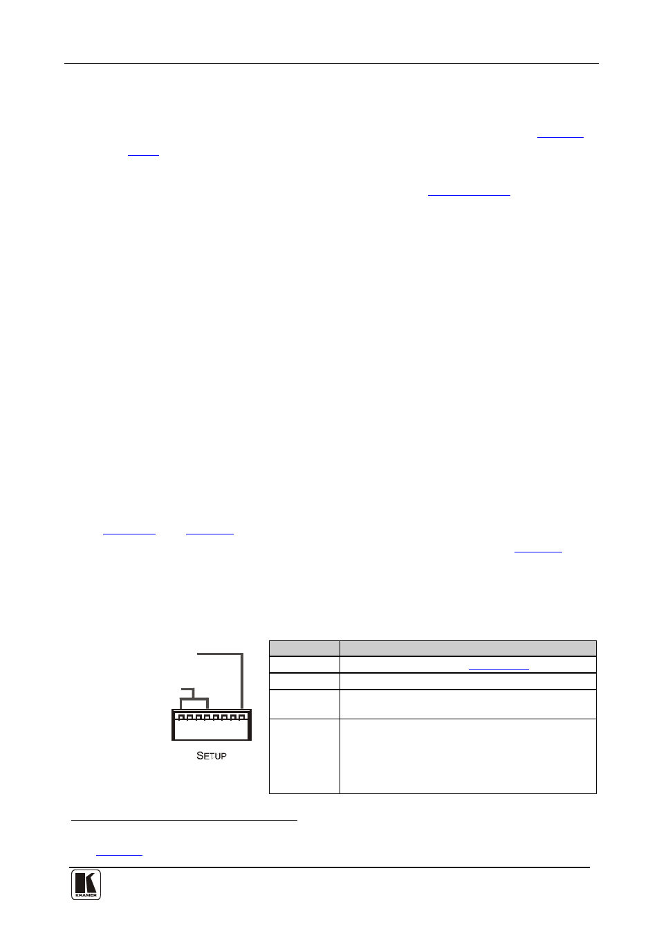
6.2 Setting the DIP-switches
.
define the VS-169TP DIP-switches. By default the
VS-169TP (when used as a single unit) is set to Machine #1 (see
).
When connecting more than one VS-169TP unit, allocate a unique Machine #
to the VS-169TP. The line termination DIP-switch is for use only with the
RS-485 port.
Machine Number
RS-232 Termination
Figure 5: DIP-switch Settings
Table 4: DIP-switch Settings
DIPS
Description
1, 2, 3, 4
Set the MACHINE # (see
Section 6.2.1
5, 6
Not used
7
Set ON to avoid having to connect a null-modem
adapter or using a null-modem connection
8
Set ON for RS-485 termination for the first and the
last machine (RS-485 line terminates with 110Ω);
for others set OFF (RS-485 line is open)
1 The cable should consist of at least three straight-through wires: PINs 2, 3 and 5
2 See