Figure 11: connecting the rs-485 connectors – Kramer Electronics VS-162AVM User Manual
Page 24
KRAMER: SIMPLE CREATIVE TECHNOLOGY
Connecting a Control Interface
20
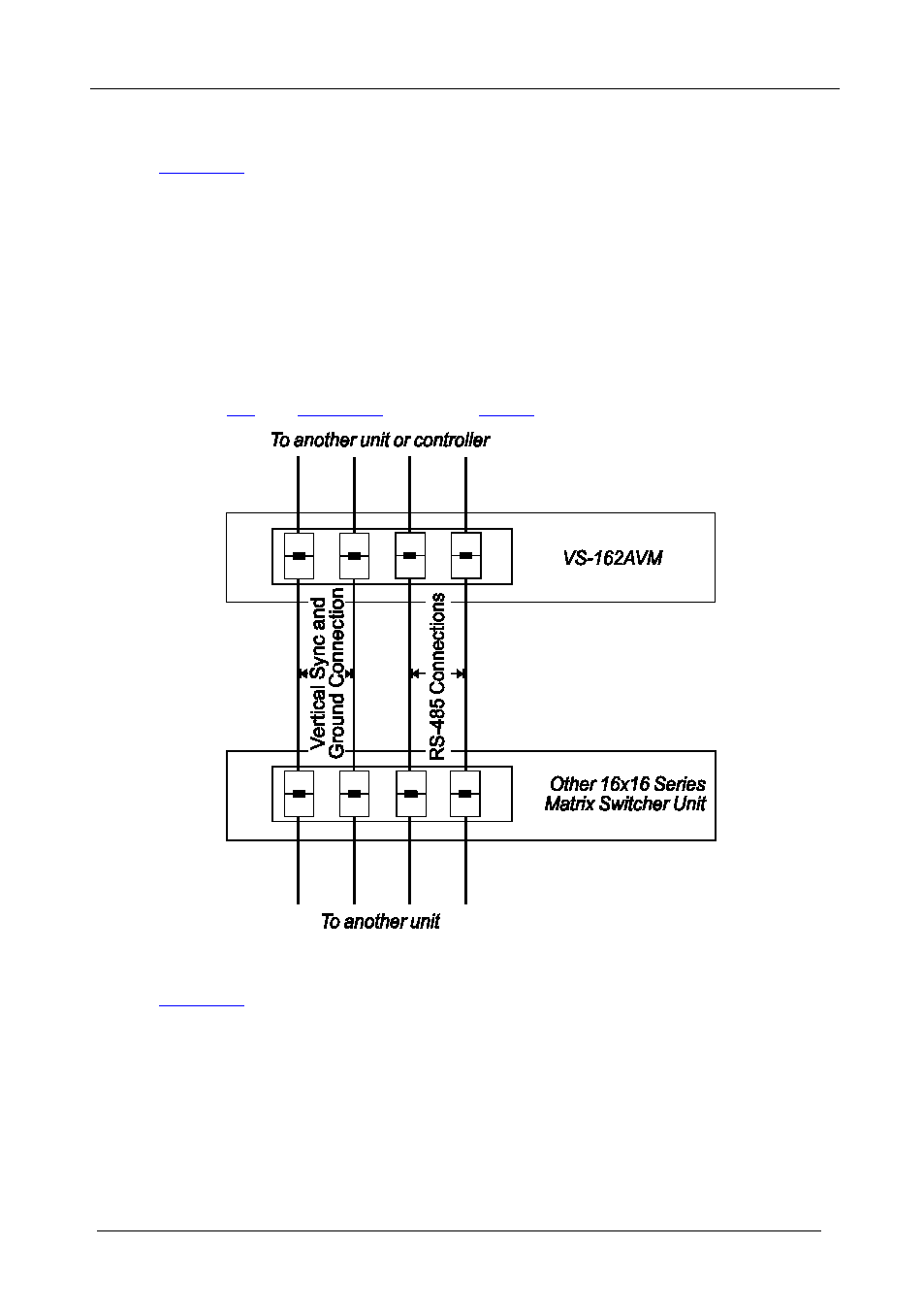
To connect an RS-485 connector on one unit to an RS-485 connector on one
or more other switchers (from the series of 16x16 matrix switchers), as
1. Connect the “+” PIN on the first unit to the “+” PIN on the second unit or
other unit
2. Connect the “-” PIN on the first unit to the “-” PIN on the second unit or
other unit
3. If shielded cable is used for an RS-485 connection, connect the shield to the
Ground PIN.
For details about how to configure the vertical sync (if required), refer to
Figure 11: Connecting the RS-485 Connectors
illustrates the RS-485 line that connects:
•
To the PC via a Kramer Tools VP-43xl Interface Converter
(connect the PC’s 9-pin D-sub COM port to the “RS-232 in” 9-pin
D-sub (F) port on the VP-43xl. Next, connect the RS-485 port on
the VP-43xl to the RS-485 ports on the unit by connecting the
“A” terminal of the VP-43xl to the “+” terminals of the switchers,
and “B” to “-” terminals)