Table 1: front panel features, Table 2: rear panel features, Table 1 – Kramer Electronics VS-162AVM User Manual
Page 11: Table 2, Your audio-video router, 7table 1: front panel features
Your Audio-Video Router
7
7
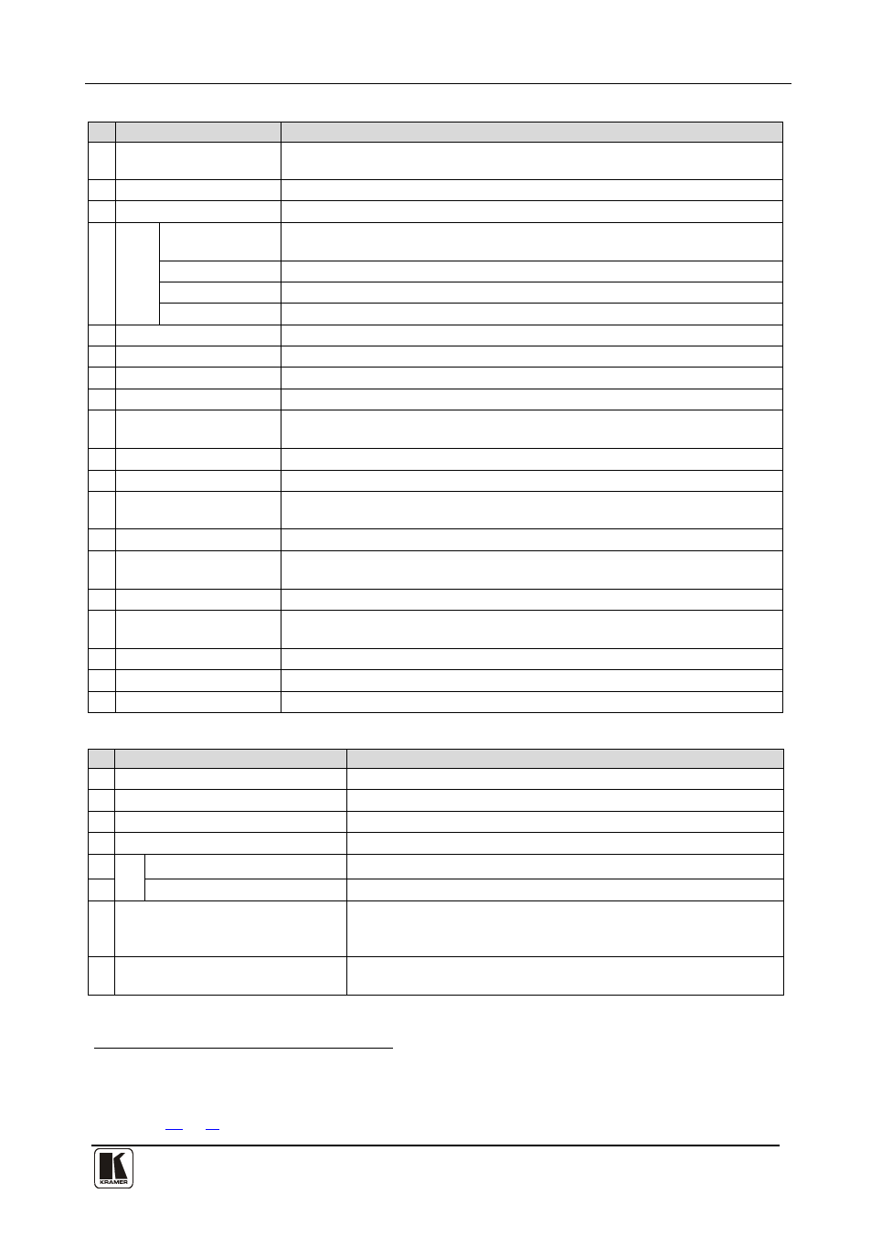
Table 1: Front Panel Features
#
Feature
Function
1 IR Receiver LED
The red LED illuminates when receiving signals from the Kramer infrared
remote control transmitter
2 IR Receiver
Receives signals from the Kramer infrared remote control transmitter
3 Preview Monitor
Displays the video routed to output 16
4
LC
D
C
ON
TR
OL
MENU Button
Press once to display the last LCD settings (brightness, contrast, saturation,
and sharpness), each additional press scrolls through the menu items
+ Button
Increases the selected setting
– Button
Decreases the last setting
POWER Button Turns the LCD display on and off
5 VOLUME Knob
Adjusts the audio level of the headphones
6 PHONES ¼” Connector Jack for connecting the headphones to audio 16 output
7 ALL Button
Pressing ALL followed by an INPUT button, connects that input to all outputs
8 VIDEO Button
When selected
9
actions relate to video independently from audio
OFF Button
An OFF-OUT combination disconnects that output from the inputs; an OFF-
ALL combination disconnects all the outputs
10 AUDIO Button
When selected
11
actions relate to audio independently from video
STO Button
Stores the current setting in the non-volatile memory
12 AFV Button
When selected actions relate to video and audio channels. Audio channels
follow the video channels, and the AFV button is illuminated
13 RCL Button
Recalls a setup from the non-volatile memory
14 LCD MATRIX Display
Displays the selected input(s) switched to the output(s) (above or below the
corresponding OUTPUT label) and user interface messages
15 LCD STATUS Display
16 OUT Buttons
Select the output to which the input is switched (1 to 15)
Preview/16 connects the input to the preview monitor
17 IN Buttons
Select the input to switch to the output (1 to 16)
18 MENU Button
Recall and navigate the menu points for matrix setting
19 TAKE Button
Used to confirm and complete setup and switching
Table 2: Rear Panel Features
#
Feature
Function
20 IN BNC Connectors
Connect to the video sources
21 OUT BNC Connectors
Connect to the video acceptors
22 IN
Terminal Blocks
Connect to the audio sources
23 OUT Terminal Blocks
Connect to the audio acceptors
24
SYN
C
IN BNC Connector
Connect to the external video sync source
25
LOOP BNC Connector
Connect to the SYNC IN connector on the next unit
26 TERM Button
Press to terminate at 75Ω or release for looping (push in to
terminate the sync line. Release when the sync line extends to
another unit)
27 EXT. (extension) KEYS Terminal
Block Connectors
Connect to an external keyboard (remote unit)
1 The VIDEO button is illuminated when the video breakaway mode is selected
2 The AUDIO button is illuminated when the audio breakaway mode is selected
3 In sections
, the word “Displays” refers to the LCD MATRIX and STATUS displays