2 setting the machine, Setting the machine, Table 4: dip-switch definitions – Kramer Electronics VS-162AVM User Manual
Page 19: Table 5: machine # dip-switch settings, Table 4, Understanding addressing and system modes, 15 table 4: dip-switch definitions
Understanding Addressing and System Modes
15
15
Table 4: DIP-Switch Definitions
DIP-switch #
Function:
1-4
Set the MACHINE # (see
5
Enables (ON) or disables (OFF) the Follow-SYSTEM mode
6
Enables (ON) or disables (OFF) the SLAVE mode in a multi-channel configuration
7
Disables use of a null modem adapter
OFF = RS-232 connection via a null modem adapter
ON = RS-232 connection without a null modem adapter
with RS-232
8
RS-485 termination for first and last machine = ON (RS-485 line terminates with
110Ω); for others = OFF (RS-485 line is open)
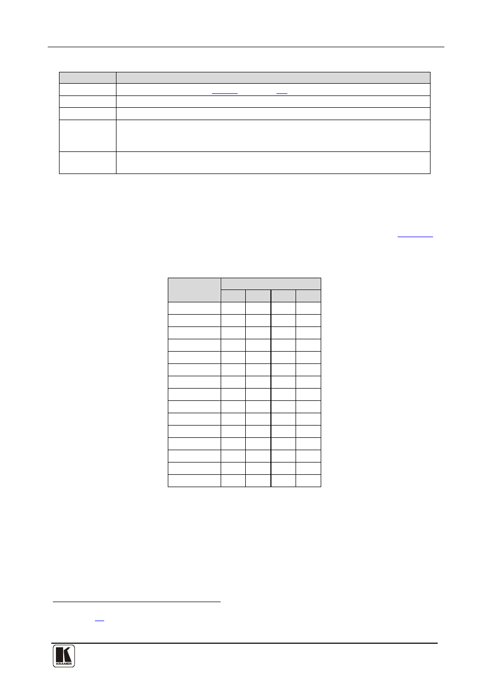
8.2 Setting the MACHINE #
To control a unit via RS-232 or RS-485, each unit has to be identified via its
unique MACHINE #. Set the MACHINE #
A valid MACHINE # is from 1 to 15.
Table 5: Machine # DIP-switch Settings
MACHINE #
DIP-SWITCH
1
2
3
4
1
ON OFF OFF OFF
2
OFF ON OFF OFF
3
ON ON OFF OFF
4
OFF OFF ON OFF
5
ON OFF ON OFF
6
OFF ON ON OFF
7
ON ON ON OFF
8
OFF OFF OFF ON
9
ON OFF OFF ON
10
OFF ON OFF ON
11
ON ON OFF ON
12
OFF OFF ON ON
13
ON OFF ON ON
14
OFF ON ON ON
15
ON ON ON ON
1 See section
2 When using a single unit, set the unit to MACHINE # 1