5 setting the vp-885 dip-switches, Setting the vp-885 dip-switches, Figure 13: vp-885 dip-switches – Kramer Electronics VP-885 User Manual
Page 22: Table 4: dip-switch settings, Table 5: machine number dip-switch settings
KRAMER: SIMPLE CREATIVE TECHNOLOGY
Connecting the VP-885
18
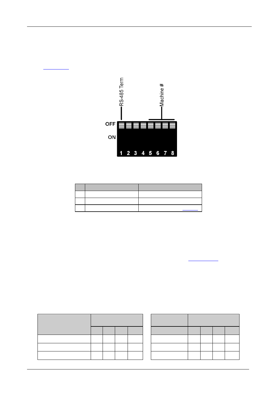
6.5 Setting the VP-885 DIP-switches
This section describes the VP-885 DIP-switch settings that configure RS-485
bus termination and the VP-885 machine number.
illustrates the factory default DIP-switch positions.
Figure 13: VP-885 DIP-switches
Table 4: DIP-switch Settings
#
DIP-switch Number
Function
1 1
RS-485 Termination
2 2, 3, 4
Not used
3 5, 6, 7, 8
Machine number (see
DIP-switch 1 determines the RS-485 bus termination for the VP-885.
DIP-switches 2, 3, and 4 are not used.
DIP-switches 5, 6, 7, and 8 determine the machine number of the VP-885.
When several VP-885 units are connected, the machine number determines
the unique identity of the VP-885 in the sequence (see
Section 6.5
).
•
When using a stand-alone VP-885 unit, set the machine number to 1
(factory default)
•
When connecting more than one VP-885, set the first machine (only
when connected via RS-232) to be machine number 1. The other VP-885
units must each be set to a unique machine number between 2 and 16.
Table 5: Machine Number DIP-switch Settings
Machine Number
DIP-switch
Machine
Number
DIP-switch
5
6
7
8
5
6
7
8
1 (Master, factory default) OFF OFF OFF OFF
9 (Slave)
ON OFF OFF OFF
2 (Slave)
OFF OFF OFF ON
10 (Slave)
ON OFF OFF ON
3 (Slave)
OFF OFF ON OFF
11 (Slave)
ON OFF ON OFF