Kramer Electronics VP-460 User Manual
Page 12
VP-460 - Overview
7
7
#
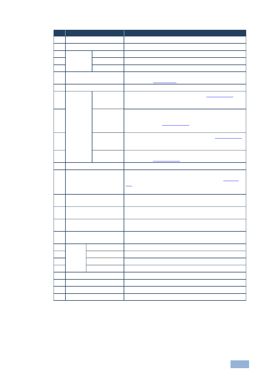
Feature
Function
1
IR Receiver
Accepts IR remote commands
2
IR LED
Lights red when the unit accepts IR remote commands
3
INPUT
SELECT
Buttons
PC
Press to select the computer graphics input
4
CV
Press to select the composite video input
5
SDI
Press to select the SDI input
6
PIP Button
Toggles the dual window mode (Picture-in-Picture)
function (see
Section 6.2
7
FREEZE Button
Press to freeze/unfreeze the output video image
8
Navigation
Buttons
/-
VOLUME
Button
Press to move down the menu list (see
Section 7.1.1
9
) and
to decrease numerical values. When not within the OSD
menu mode, press to reduce the output volume
Button
Press to access the OSD menu, exit the OSD menu and,
when in the OSD menu, move to the previous level in the
OSD screen (see
Section 7.1.1
10
/+
VOLUME
Button
Press to move up the menu list values (see
Section 7.1.1
11
and to Increase numerical values. When not within the
OSD menu mode, press to increase the output volume
ENTER
Button
Press to access sub-menu items and select from several
settings (see
Section 7.1.1
12
MENU Button
Press to access/exit the menu
13 RESET TO 720P Button
Press to reset the video resolution to 720p and change
the deep color settings to off on the output (see
Section
Press and hold for about 3 seconds to reset to 720p
14 PANEL LOCK Button
Press and hold for about 2 seconds to lock/unlock the
front panel buttons
15 AUDIO PC IN 3.5mm Mini
Jack Connector
Connect to the unbalanced audio of the computer
graphics source
16 AUDIO CV IN (L, R) RCA
Connector
Connect to the unbalanced stereo audio of the composite
video source
17 AUDIO S/PDIF OUT RCA
Connector
Connect to a digital audio acceptor
18
V
ID
E
O
INP
UT
C
onn
ec
tor
s PC IN 15-pin HD Connect to the computer graphics source
19
CV IN RCA
Connect to the composite video source
20
SDI IN
Connect to the SDI source
21
SDI LOOP
Connect to a local display
22 HDMI OUT Connector
Connect to an HDMI acceptor
23 RS-232 9-pin D-sub Port
Connect to the PC or the remote controller
24 SDI OUT BNC Connector Connect to an SDI acceptor
25 5V DC
+5V DC connector for powering the unit