A.3.2, Increment generator input [x2, A.3.3 – Festo Контроллеры двигателя CMMS-ST User Manual
Page 131: Can bus [x4, A.3.4, Rs232/rs-485 [x5, A.3.2 increment generator input [x2, A.3.3 can bus [x4
A. Technical data
Festo.P.BE-CMMS-ST-G2-HW-EN 1008NH
131
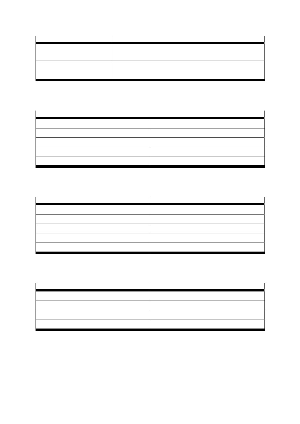
Analogue inputs/outputs
Values
High-resolution analogue input:
AIN0
±10 V input section, 12 bit, differential,
< 250 μs delay time
Analogue outputs:
AOUT0 and AOUT1
±10 V output range, 9 bit resolution, f
limit
> 1 kHz
Table
A.11 Technical data: Analogue inputs and outputs [X1]
A.3.2 Increment generator input [X2]
Increment generator input
Values
Signal level of tracking signals A, B, N
5 V differential, RS422
Angle resolution
Max. 12 bit
Number of lines of the increment generator
500
Limit frequency
> 100 kHz
Encoder supply
5 V ±5% 100 mA
Table
A.12 Increment generator input [X2]
A.3.3 CAN bus [X4]
Communication interface
Values
Signal level
±2 V
Protection
-3 … +24 V
Protocol CANopen
CiA
DS
301, CiA DSP 402 and FHPP
Baud rate
Max. 1 MBaud
Terminating resistor
120 Ω
Table
A.13 Technical data: CAN bus [X4]
A.3.4 RS232/RS-485 [X5]
Communication interface
Values
RS232 According
to
RS232 specification
RS-485
According to RS-485 specification
Baud rate
9600 … 115 kBaud
Protection
ESD protected driver
Table
A.14 Technical data: RS232 [X5]