To set the shock absorber – Festo Cтопорный цилиндр DFST User Manual
Page 22
DFST
Festo DFST 0710NH
22
S
Start a test run as follows:
DFST is inserted
Reaction
double−acting
single−acting
Pressurise stroke air
connection
1
Pressurise stroke air
connection
2
The piston rod extends.
Approach DFST with medium stream
The approaching medium stream is slowed and
pushes the toggle lever into its rear end position
(toggle lever engages at DFST−...−L).
Pressurise stroke air connection
2
The piston rod retracts. The toggle lever locking
mechanism is unlocked (at DFST−...−L). The
medium stream is transported onwards.
Pressurise stroke air
connection
1
Pressurise stroke air
connection
2
The piston rod extends. The DFST can slow the
next medium stream.
Fig. 20
To unlock the
toggle lever locking mechanism at DFST−...−L (è Accessory):
S
Pressurise stroke air connection
2.
When the piston rod is retracted, the
toggle lever locking mechanism pushes
the top side of the flange (and/or the
screw head on DFST−63/80) and releases
the toggle lever.
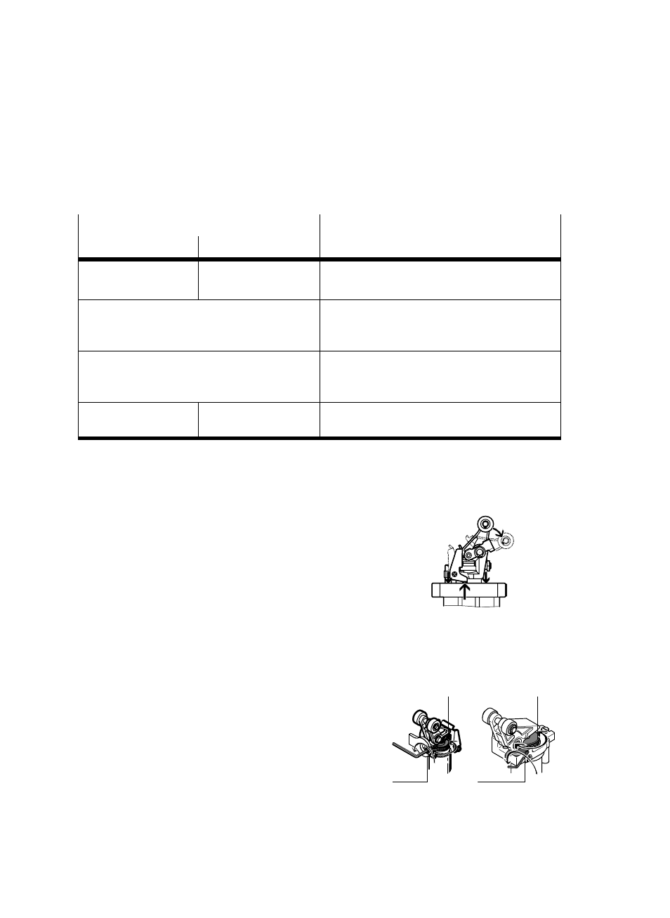
To set the
shock absorber:
S
Slacken the counterscrew (A)
(withĂcounternut on DFST−50).
S
Turn the knurled nut
7 until the required
cushioning has been reached.
If the setting is correct, the medium
stream will gradually push through and
come to a standstill.
Fig. 21
Fig. 22
7
(A)
7
DFST−50
DFST−63/80
(A)