Pr n, Atvn, Xyst – NOVUS Controller N2000S User Manual
Page 5: Sert, Serr, Serf, Sp.a1, Tbas, Ptol, Psp0
Controller N2000S
NOVUS AUTOMATION
5/9
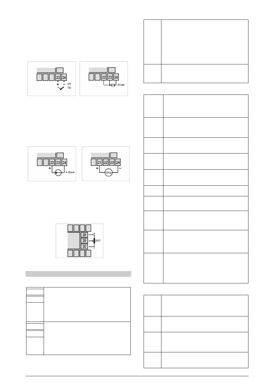
INPUT CONNECTIONS
It is important that they are very well connected; the sensor wires
must be well fixed in the terminals of the rear panel.
•
Thermocouple (T/C) and 50 mV:
Figure 3 shows how connections are made. If extension of the
thermocouple is required, proper compensation cables should be
provided.
Figure 3 – Thermocouple and 0-50
mV
Figure 4 - Pt100 wiring with three
conductors
•
RTD (Pt100):
Figure 4 shows the Pt100 wiring for 3 conductors. Terminals 22, 23,
and 24 must have the same wire resistance for proper cable length
compensation (use conductors with the same gauge and length). In
case the sensor has 4 wires, one should be left loose near the
controller. For 2-wire Pt100, short circuit terminals 22 and 23.
Figure 5 – Connection of 4-20 mA
Figure 6 – Connection of 5 Vdc
•
4-20 mA: Figure 5 shows the 4-20 mA current signals wiring.
•
0-5 Vdc: Figure 6 shows the 0-5 Vdc voltage signals wiring.
•
Alarm and output connection
When I/O channels are set up as output channels, they must have
their capacity respected, according do specifications.
Figure 7 – Potentiometer connection
CONFIGURATION PARAMETERS
OPERATION CYCLE
PV Indication
(Red)
SV Indication
(Green)
PV and SP indication: The upper status display shows the
current value of PV. The lower parameter display shows SP
value of automatic control mode.
The upper display shows “- - - -“ whenever PV exceeds the
maximum range or there is no signal at the input. In case of
hardware error the status display will show “Er
Er
Er
Er n
n
n
n”, where n
is the error code.
PV Indication
(Red)
MV Indication
(Green)
MANIPULATED VARIABLE VALUE (MV) (control output):
The upper display shows PV value and the lower display
shows the percentage of MV applied to the control output.
When in manual control, the MV value can be changed.
When in auto mode, the MV value is only for visualization.
To distinguish the MV display from the SP display, the MV
flashes intermittently.
Pr n
Pr n
Pr n
Pr n
Program
number
PROGRAM EXECUTION: Selects the ramp and soak
program to be executed.
0 – does not run program
1, 2, 3, 4, 5, 6 and respective program.
When the control is enabled, the program selected runs
immediately.
In the program cycle of ramp and soak there is a parameter
with the same name. In that context, the parameter is
associated with the number of the program that will run.
rvn
rvn
rvn
rvn
ENABLES CONTROL AND ALARMS OUTPUT:
YES - control and alarm enabled;
NO - control and alarms enabled.
TUNING CYCLE
atvn
atvn
atvn
atvn
(Auto-tune) – auto tune of PID parameters. See item 9 in this
manual.
YES – Enables auto tune.
NO – Disables auto tune.
Pb
Pb
Pb
Pb
(Proportional band) – PROPORTIONAL BAND: P term
value of the PID control, percentage of maximum input type
span. Adjustable between 0 and 500 % If adjusted to
zero, control is ON/OFF.
xyst
xyst
xyst
xyst
(HYSteresis) – CONTROL HYSTERESIS: Hysteresis value
for ON/OFF control. This parameter is shown only for
ON/OFF control (Pb=0).
Ir‘
Ir‘
Ir‘
Ir‘
(integral rate) – INTEGRAL RATE: Value of I term of PID
control in repetetions per minute (Reset). Adjustable
between 0 and 24.00. Presented if proportional band
≠
0.
dt
dt
dt
dt
(derivative time) - DERIVATIVE TIME: Value of D term of
the PID control in seconds. Adjustable between 0 and 250
s. Presented if proportional band
≠
0.
sert
sert
sert
sert
(Servo time) – time of servo excursion, from totally open to
totally closed. Programmable from 15 to 600 s.
serr
serr
serr
serr
(Servo resolution) – control resolution, determines the dead
band of servo activation. Very low values (<1 %) make the
servo “nervous”
serF
serF
serF
serF
(Servo filter) – PID output filter, before use by the servo
control. It is the time the PID mean is made, in seconds.
The output is only activated after this time. Recommended
value: > 2 s.
act
act
act
act
(Action) – CONTROL ACTION: Only in the automatic control
mode
Reverse action (“ rE
rE
rE
rE “) usually used for heating;
Direct action (“ rE “) usually used for cooling
Sp.a1
Sp.a1
Sp.a1
Sp.a1
Sp.a2
Sp.a2
Sp.a2
Sp.a2
(SetPoint of Alarm) – ALARM SP: Value that defines the
trigger point of alarms programmed with the “Lo” or “Hi”
functions. In alarms programmed with the function
Differential this parameter defines the deviation. See item
5.3.
It is not used in other alarm functions.
PROGRAM CYCLE
tbas
tbas
tbas
tbas
TIME BASE: Selects the time base for the ramp and soak.
Valid for all profile programs.
0
0
0
0
- PT1 to PT7 values are in seconds;
1
1
1
1 - PT1 to PT7 values are in minutes;
Pr n
Pr n
Pr n
Pr n
(Program number) – PROGRAM EDITING: Selects the ramp
and soak program to be edited in the next prompts of this
cycle.
Ptol
Ptol
Ptol
Ptol
(Program tolerance) – PROGRAM TOLERANCE: Maximum
deviation between PV and SP. Whenever this deviation is
exceeded the time counter is halted until deviation lowers to
acceptable values. Set zero to disable this function.
Psp0
Psp0
Psp0
Psp0
Psp7
Psp7
Psp7
Psp7
(Program SetPoint) – PROGRAM SPs, 0 TO 7: Set of 8 SP
values that define the ramp and soak program profile (see
item 8).