Installation / connections – NOVUS Controller N2000S User Manual
Page 4
Controller N2000S
NOVUS AUTOMATION
4/9
•
Minimum differential
It is activated when the measured value is below the value defined in.
(SP - Deviation)
•
Maximum differential
It is activated when the measured value is above the value defined in:
(SP + Deviation)
ALARM TIMER
Alarms can be programmed to have timer functions. The user can
delay alarm activation, set one pulse per activation, or make the
alarm signals operate in sequential pulses. Alarm timer is available
only for alarms 1 and 2 when “A1t1
A1t1
A1t1
A1t1”, “A1t2
A1t2
A1t2
A1t2”, “A2t1
A2t1
A2t1
A2t1” and “A2t2
A2t2
A2t2
A2t2
parameters are programmed.
Figures shown in Table 4 represent these functions, t 1 and t 2 may
vary from 0 to 6500 seconds and their combinations define the timer
mode. For normal operation, with no alarm timer activation, t 1 and t 2
must be assigned 0 (zero).
The LEDs associated to the alarms will flash whenever an alarm
condition is acknowledged, regardless the actual state of the output
relay, which may be temporarily off because of temporization.
ALARM INITIAL BLOCKING
The initial blocking option prevents the alarm from being recognized if
an alarm condition is present when the controller is turned of for the
first time. The alarm could be activated only after the occurrence of a
non-alarm condition followed by a new occurrence of an alarm
condition. The initial blocking is useful, for example, when one of the
alarms is programmed as minimum value alarm, which can trigger the
alarm at the system startup. This is not always required.
The initial blocking is disabled for the open sensor function.
ALARM
FUNCTION
t1
t2
ACTION
Normal
0
0
Alarm Event
Alarm
Output
Delayed
0
1 to 6500 s
Alarm Event
Alarm
Output
T2
Pulse
1 to 6500 s
0
Alarm Event
Alarm
Output
T1
Oscillator
1 to 6500 s 1 to 6500 s
Alarm Event
Alarm
Output
alarme
T1
T2
T1
Table 4 – Temporization functions for Alarms 1 and 2
PV AND SP ANALOG RETRANSMISSION
The controller has an analog output (I/O5) that can make a 0-20 mA
or 4-20 mA retransmission proportional to the PV or SP values
assigned. The analog retransmission is scalable, this means it has
max. and min. limits that define the output range, which can be
defined in parameters “SPLL
SPLL
SPLL
SPLL” and “SPkL
SPkL
SPkL
SPkL”.
To obtain voltage retransmission the user must install a shunt resistor
(550
Ω
max.) in the analog output terminal. The resistor value
depends on the voltage range required.
F
KEY FUNCTIONS
F
key (special function key) in the frontal panel of the controller can
perform the same function as the Digital Input I/O6 (except function
6). The key function is defined by the user in the “fFvn
fFvn
fFvn
fFvn” parameter:
0
0
0
0 -
Disables the alarm;
7
7
7
7 – Defines the channel for the digital input and turns off the
(“RvN
RvN
RvN
RvN”: YES / no) control.
Closed = enabled outputs
Open = control output and alarms turned off;
8
8
8
8 – Invalid selection;
9
9
9
9 – Defines the channel that will command programs execution
Closed = enables program execution
Open = interrupts program
Note: When the program is interrupted, execution is held (the control
remains active). The program resumes when the signal applied to the
digital input allows it (closed contact).
10
10
10
10 – Defines channel to select program 1. This option is useful
when the user wants to switch between the main setpoint and
a second one defined in the program of ramp and soak.
Closed = selects program 1;
Open = takes the main setpoint
Note: When a function is selected to operate through digital
input, the controller does not respond to the equivalent function
command given in the frontal keypad.
KEY
The
key is located in the frontal panel. It performs function 6 of
the digital input I/O6: switch between automatic and manual control.
Operation of this key is enabled in parameter aven.
aven.
aven.
aven.
The MAN indicator flashes when the manual control mode is
selected.
INSTALLATION / CONNECTIONS
PANEL MOUNTING
The controller must be panel-mounted following the steps presented
below:
1.
Make the panel slot;
2.
Remove fixing brackets;
3.
Insert the controller into the panel slot;
4.
Replace the clamps in the controller pressing it to reach a
firm grip at the panel.
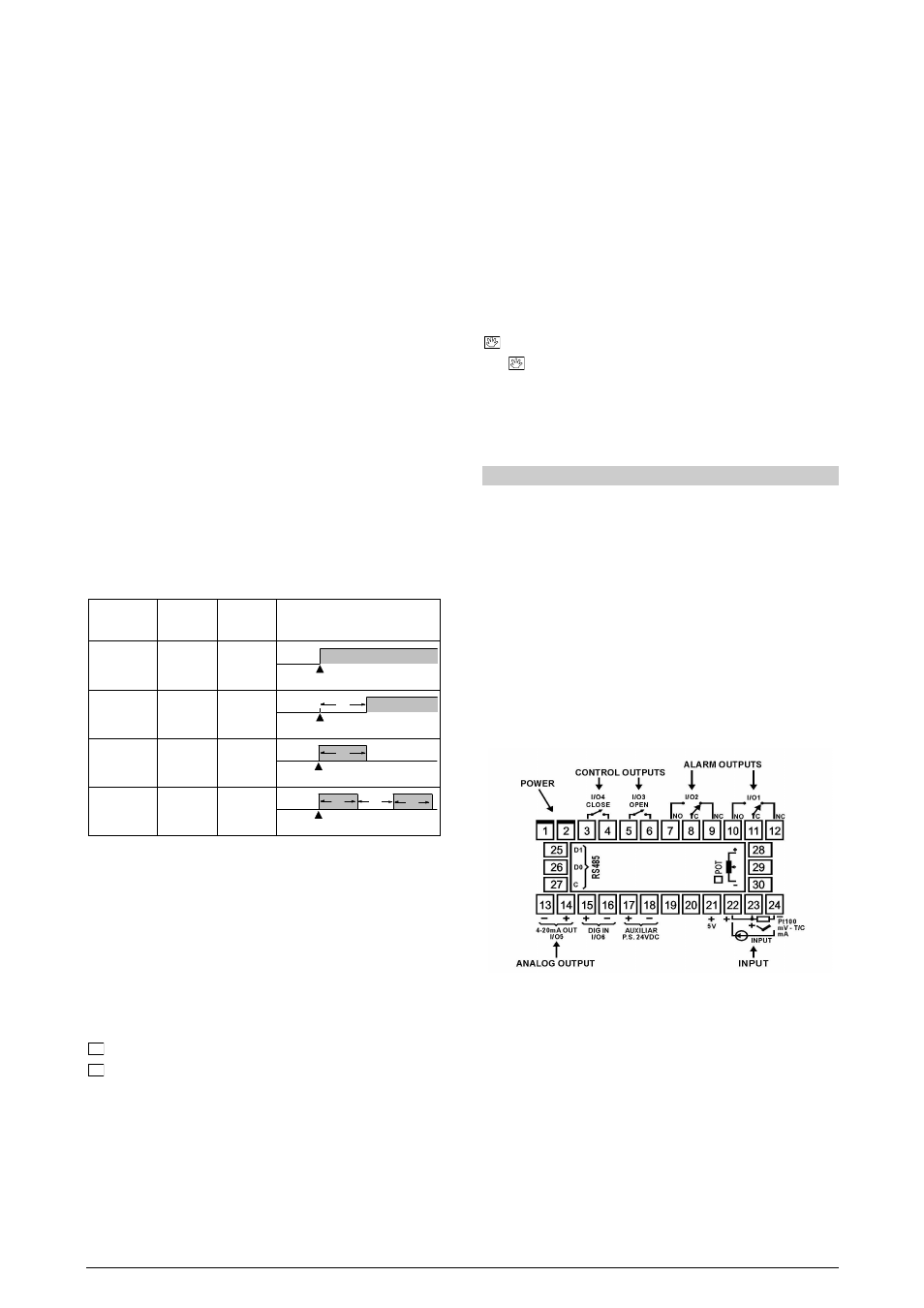
ELECTRICAL CONNECTIONS
It is not necessary to disconnect the rear panel terminals to remove
the internal circuit. Figure 2 shows how signals are distributed in the
controller rear panel.
Figure 2 – Rear panel terminals
INSTALLATION RECOMMENDATIONS
•
Conductors of input signals must be distant from activation or
high-tension/current conductors, preferably passing through
grounded conduits.
•
A specific electrical power supply network should be provided for
instruments use only.
•
In
controlling
and
monitoring
applications,
possible
consequences of any system failure must be considered in
advance. The internal relay alarm does not provide total
protection.
•
RC filters (for noise reduction) in inductor charges (contactors,
solenoids, etc.) are recommended.