Configuration / resources – NOVUS Controller N2000S User Manual
Page 2
Controller N2000S
NOVUS AUTOMATION
2/9
Other special functions, including ramp and soak, alarm timer, digital
input, etc., can be used to achieve better performance.
The setup parameters are grouped in cycles, in which each message
is a parameter to be defined. The 7 parameter cycles are:
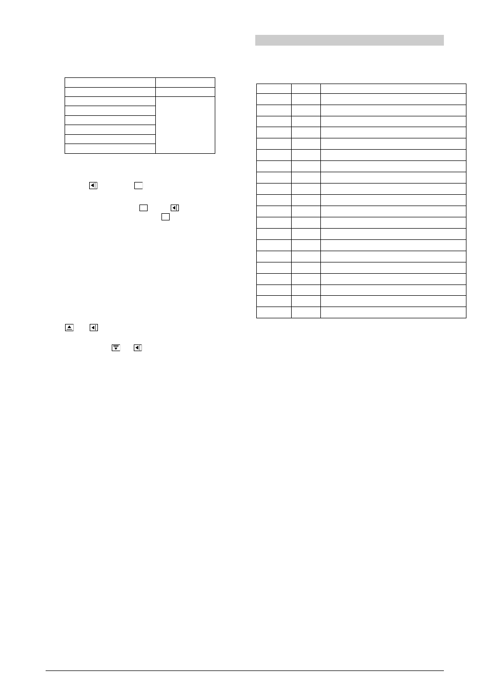
CYCLE
ACCESS
1 - Operation
Free
2 - Tuning
3 - Programs
4 - Alarms
Reserved access
5 - Input configuration
6 - I/Os
7 - Calibration
The operation cycle (1
st
cycle) is freely accessed. The other cycles
require a keystroke combination to enable access.
Press
(BACK) and
P
(PROG) simultaneously
When the required cycle is found, all the parameters within this cycle
can be accessed by pressing the
P
key (or
, to go backwards).
To return to the operation cycle, press
P
many times up to all
parameters of the current cycle have been shown.
All parameters set up are stored in a protected memory. Changed
values are automatically saved when the user goes to the next
parameter. The SP value is saved when parameters are changed or
at every 25 seconds.
CONFIGURATION PROTECTION
The parameter values can be locked after configuration is finished
thus preventing undesirable changes. Parameters can be seen but
not changed. Protection is activated by a combination of keystrokes
and a internal key.
Press
and
simultaneously for 3 seconds, in the cycle you
want to protect.
To unlock a cycle press
and
simultaneously for 3 seconds.
Displays will flash briefly to confirm locking or unlocking
operation.
Within the controller, the PROT key completes the locking function.
When PROT is OFF the user is allowed to lock and unlock the
cycles. When PROT is ON changes are not allowed: if cycles are
protected protection cannot be removed, if there aren’t cycles
protection, they cannot be made.
CONTROL OPERATION
The controller is based on the "SErt
SErt
SErt
SErt" parameter (Time of serve
excursion). This is the time the serve requires to open completely
when it is in the closed position. The output percentage calculated by
the PID (0 to 100 %) is transformed into the serve activation time to
reach a relative position.
A new output value of the PID is calculated at every 250 ms. The
"SErF
SErF
SErF
SErF" parameter defines the time in seconds for the calculation and
activation of a new output value. This parameter works as a filter, it
makes the output slower and increases the time intervals.
The minimum resolution for a new position change is given by the
parameter "SErr
SErr
SErr
SErr". If the difference between the current output value
and the new value calculated by the PID is lower than the
programmed percentage of this parameter, no activation is
performed.
If the calculated output is between 0 % or 100 % and it is maintained
for some time, the opening relay (when in 0 %) or the closing relay
(when in 100 %) will be periodically activated for a time fraction to
assure that the real position is close to the estimated position, for
mechanical problems or non-linearity of the process.
CONFIGURATION / RESOURCES
INPUT TYPE SELECTION
The input type must be selected by the user in the “Type” parameter
using the keyboard (see input types in Table 1).
TYPE
CODE
FEATURES
J
0
0
0
0
Range: -50 to 760 °C (-58 to 1400 ºF)
K
1
1
1
1
Range: -90 to 1370 °C (-130 to 2498 ºF)
T
2
2
2
2
Range: -100 to 400 °C (-148 to 752 ºF)
N
3
3
3
3
Range: -90 to 1300 °C (-130 to 2372 ºF)
R
4
4
4
4
Range: 0 to 1760 °C (32 to 3200 ºF)
S
5
5
5
5
Range: 0 to 1760 °C (32 to 3200 ºF)
Pt100
6
6
6
6
Range: -199.9 to 530.0 °C (-199.9 to 986.0 ºF)
Pt100
7
7
7
7
Range: -200 to 530 °C (-328 to 986 ºF)
4-20 mA
8
8
8
8
J Linearization. Programmable range: -110 to 760 °C
4-20 mA
9
9
9
9
K linearization Programmable range: -150 to 1370 °C
4-20 mA
10
10
10
10
T linearization. Programmable range: -160 to 400 °C
4-20 mA
11
11
11
11
N linearization Programmable range: -90 to 1370 °C
4-20 mA
12
12
12
12
R linearization Programmable range: 0 to 1760 °C
4-20 mA
13
13
13
13
S linearization Programmable range: 0 to 1760 °C
4-20 mA
14
14
14
14
Pt100 linearization. Prog. range: -200.0 to 530.0 °C
4-20 mA
15
15
15
15
Pt100 linearization. Prog. range: -200 to 530 °C
0 – 5 0 mV
16
16
16
16
Linear. Programmable indication from –1999 to 9999.
4-20 mA
17
17
17
17
Linear. Programmable indication from –1999 to 9999.
0 – 5 Vdc
18
18
18
18
Linear. Programmable indication from –1999 to 9999.
4-20 mA
19
19
19
19
Input square root extraction
Table 1 – Input types
Note: All available input types are factory calibrated.
I/O CHANNELS CONFIGURATION
The controller input/output channels can undertake multiple functions:
Control output, digital input, digital output, alarm output, PV and SP
retransmission. These channels are identified as I/O 1, I/O2, I/O 3,
I/O 4, I/O 5 and I/O6.
The function code of each I/O can be selected among the following
options. Only valid function codes are displayed for each I/O.
I/O 1 and I/O2 – used as ALARM outputs
Two SPDT relays are available in terminals 7 to 12. They can be
assigned codes O, 1 or 2.
0
0
0
0 - Disables the alarm;
1
1
1
1 - Defines channel as alarm 1;
2
2
2
2
- Defines channel as alarm 2;
I/O 3 and I/O4 – used as CONTROL outputs
Two SPST relays, available in terminals 3 to 6. They are assigned
code 5.
5
5
5
5 – Defines channel as control output.
I/O 5 – Analog output and digital input
0-20 mA or 4-20 mA analog channel output used to retransmit PV
and SP values, or perform functions of digital input and output. They
can be assigned codes 0 to 16.
0
0
0
0 – No function (disabled);
1
1
1
1 – Defines channel as alarm 1;
2
2
2
2 – Defines channel as alarm 2;
3
3
3
3 – Invalid selection;
4
4
4
4 – Invalid selection;
5
5
5
5 – Invalid selection;
6
6
6
6 -
Digital input, manual/automatic selection:
Closed = manual control;
Open = automatic control