Im-366 – American Electric Lighting IM-366 User Manual
Page 4
IM-366
2.2.5
Energize the floodlight. Check its operation and check for
proper area illumination. Adjust the aiming point as needed within the
limits of the mounting restrictions.
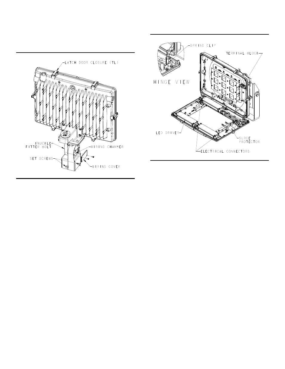
Figure 3
GR2277
2.3 Knuckle Fitter Mount Installation
This luminaire is pre-wired with UL listed supply wire leads, so it is not
necessary to open the housing door to install or wire the luminaire. If
access to the interior of the housing is necessary, refer to the
MAINTENANCE section (SECTION 3) below.
2.3.1
Slip the slip fitter of the knuckle fitter over the pole-top, tenon or
pipe bracket. Lightly tighten all four set screws evenly against the pole-
top, tenon or pipe bracket.
WARNING
DO NOT MOUNT THE KNUCKLE FITTER TO A TENON OR
BRACKET THAT IS MORE THAN 30 DEGREES FROM
VERTICAL. MOUNTING AT AN ANGLE GREATER THAN 30
DEGREES MAY RESULT IN DISENGAGEMENT OF THE
FITTER AND RESULT IN SERIOUS INJURY OR DEATH.
2.3.2
Removed wiring cover from knuckle fitter.
2.3.3
Make all wiring connections inside the wiring chamber in
accordance with approved wiring methods.
2.3.4
Replace the knuckle fitter wiring cover.
2.3.5
Aim the floodlight restricting mounting to ± 90° from vertical
aim. For units with a photocontrol receptacle, the mounting must be
restricted to ± 45° from vertical aim.
2.3.6
Tighten the 3/8" diameter knuckle fitter bolt securely (approx.
16 ft.lb. recommended). Tighten (4) 3/8 set screws to 16 ft.lb. See
Figure 3.
2.3.7
Energize the floodlight. Check its operation and check for
proper area illumination. Adjust the aiming point as needed within the
limits of the mounting restrictions.
Figure 4
GR2278
2.4 DM Option
For units equipped with 0-10V dimming, locate the gray and violet
leads in the knuckle wiring chamber or inside the unit for the yoke
mount options. These are to be used with an AEL approved control
circuit. Connect supply dimming leads to dimming leads in the wiring
chamber next to the terminal block. VIOLET IS POSITIVE, GRAY IS
NEGATIVE.
CAUTION
IT IS NECESSARY THAT THE POLARITY OF THE DIMMING
CONTROL LEADS TO THE FIXTURE BE MAINTAINED.
CROSSING OF THE POLARITY WILL CAUSE IMPROPER
AND UNEXPECTED DIMMING RESULTS AND MAY LEAD
TO DAMAGE TO THE DRIVER DIMMING CIRCUITS.
3
MAINTENANCE
3.1 Cleaning of Luminaire
3.1.1
Wipe off exterior dirt and debris using a soft clean cloth. A mild
detergent and water may be used if necessary.
CAUTION
DO NOT USE ABRASIVE CLEANERS ON OPTICAL
SURFACES. THEIR USE MAY RESULT IN THE LOSS OF
OPTICAL EFFICIENCY.
3.2 Electrical Component Replacement
Replacement of any electrical components (with the exception of the
photocontrol) requires entry into the housing to access them. Assure
that power has been shut off before attempting to open the door.
The door is sealed with a one-piece silicone gasket. Take precaution
while opening the door not to damage or disturb the gasket.
The access door to your luminaire is normally fastened to the housing
with captive socket head cap screws; however, your luminaire may be
equipped with over-center latches for tool-less access. The door also
has twin pivot hinges to hold the door to the housing. Take precaution