2 route planning, 3 system planning, 2 route – Karcher IV 100 - 55 M B1 User Manual
Page 8: Planning, 3 system, 2 route planning 8.3 system planning
8
English 5.906-587.0 Rev. 00 (05/14)
Note
The objective is to keep the resistance in the pipeline sys-
tem as small as possible.
–
Always choose the shortest possible way.
–
Course as straight as possible with as few cracks and
bends as possible.
–
Use of the ways of other supply runs e.g. of present
pipelines, cable runs etc.
–
No obstruction of ways or systems.
–
Provide for easily accessible cleaning opening.
–
Optimum installation height is 2-3 m.
–
Plan the junctions on the same height or with a slight in-
cline to the main line.
–
Always align Y-pieces to the side, never towards the
top or bottom (medium can drain).
–
The overall cross section of the nozzle at the machine
to be vacuumed off and its branch should not exceed
the cross sectional area of the suction stub at the vac-
uum cleaner.
–
The suction stub at one single machine must not be
larger than the total connection cross section at the
vacuum cleaner.
–
90° junctions (tees) must be avoided in general.
–
With longer branch lines the cross section of the pipe-
line should be chosen larger than the suction nozzle
connection.
–
A taper of the pipe cross section must only be designed
smaller from the vacuum cleaner to the vacuuming
points and should be as close as possible to the vacu-
uming point.
–
Every vacuuming point should be equipped with a lock-
ing slide that is always closed after the switch-off of the
machine or the end of the suction process.
–
Hoses have a high pressure loss due to their large fric-
tional resistance. Due to this circumstance, the hose
lengths must be reduced to a minimum.
–
Always use a hose sleeve at the end of the hose, and
earth the wire helix of the hose on the hose sleeve by
means of a screw in order to create a potential equali-
sation.
–
All pipelines must be connected in an electrically con-
ductive way from the machine branch to the intercept-
ing pipe.
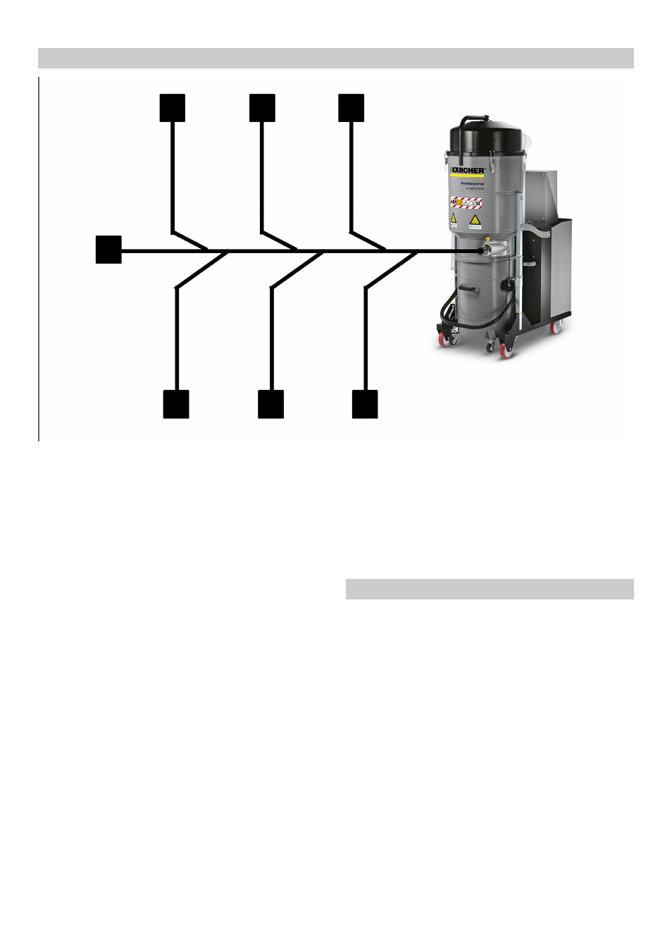
With the 4 given framework requirements a rough planning
of the stationary system can take place.
1 Spatial conditions.
2 Number of the overall and the simultaneously working
vacuuming points.
3 Required air speed.
4 Kärcher vacuum and pipeline programme.
Part one "Design pipe system" of the calculation tool for
stationary vacuuming systems can be used for the calcu-
lation of the pipe diameter (see Chapter "Calculation tool
pipe system design").
The inner diameter is calculated respectively and the pipe
closest to the calculated diameter is chosen.
With the fixed pipeline diameter the air speed actually
achieved must be calculated again.
If it does not suffice for the material to be vacuumed, the
pipeline must be redesigned or a more powerful vacuum
cleaner must be used.
8.2
Route planning
8.3
System planning