Step 4 - select power scheme, Hi-o networked controller & reader, Installation guide 4 – HID EDGE EVO EHR40-EHRP40 Reader-Controller Installation Guide User Manual
Page 4
Hi-O Networked Controller & Reader
EHR40 AND EHRP40
82000-922 D.0
INSTALLATION GUIDE
4
©2009 - 2012 HID Global Corporation. All rights reserved.
Directly connect the door peripherals identified in “Step 1 - Identify System Components” on page 2 to the I/O ports
of the EDM-M. Consult the EDM-M datasheet to determine the available current capacity for the selected input power
scheme of the EHR40 / EHRP40.
Ensure all door peripherals connected to the Strike/AUX relays and the Reader DC PWR Output or both do not exceed
1.125 Amps (AUX Input) or 0.35 Amps (PoE Input) combined. Alternatively, connect the door peripherals to the Strike/
AUX relays configured for Dry contact up to 2 Amps per relay.
Step 4 - Select Power Scheme
Select the appropriate power scheme to meet overall current draw. Using the analysis from the previous sections equates to the
following power scheme possibilities.
Power Scheme
Details
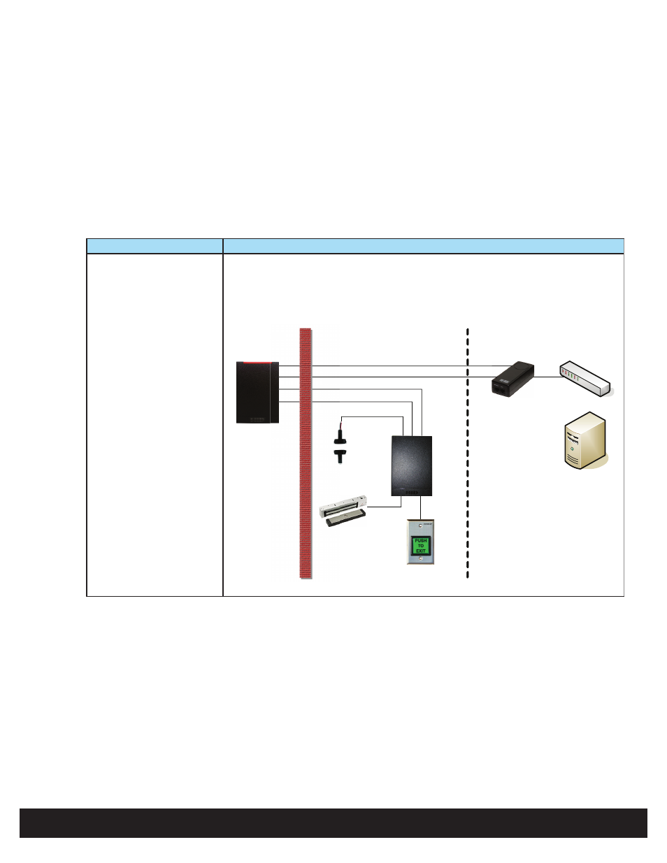
1
Hi-O Networked Controller & Reader power derived from PoE.
• Hi-O CANbus connections to the Hi-O Networked Controller & Reader include the
CAN V+ and CAN GND output connections.
• Insert a UL294 Listed PoE Injector in the Ethernet line to power the Hi-O Networked
Controller & Reader.
Protected Area
Remote Area
CANbus Data
Ethernet Data
Door Position
Switch
Magnetic Lock
REX Switch
Hi-O Networked
Controller & Reader
Door
Module
Unprotected
Area
CANbus Power (+24V)
Ethernet Power
CANb
Ethern
Door P
Sw
Magne
rked
Reader
cted
CANb
Ethern
Physical Access
Control Server
(real-time functions
not required )
Ethernet Switch
UL 294 PoE
Injector