Step 3 - analyze power requirements, Hi-o networked controller & reader, C - compute and compare overall current draw – HID EDGE EVO EHR40-EHRP40 Reader-Controller Installation Guide User Manual
Page 3
82000-922 D.0
INSTALLATION GUIDE
3
©2009 - 2012 HID Global Corporation. All rights reserved.
Hi-O Networked Controller & Reader
EHR40 AND EHRP40
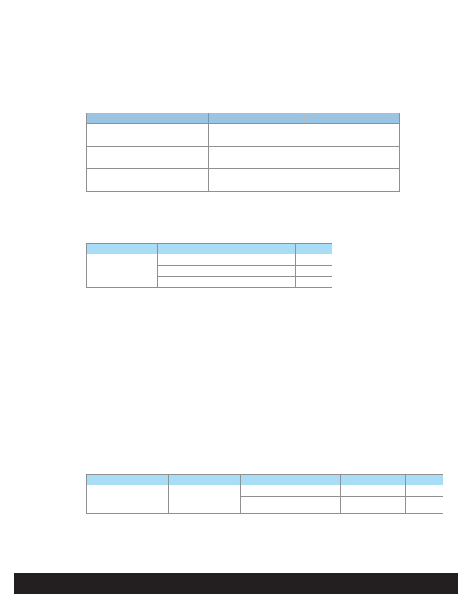
Step 3 - Analyze Power Requirements
A - Door Peripheral Operational Currents
Note: See individual peripheral data sheets for actual operational current draw..
Device
Conditions
Typical Operational Current
Door Position Switch
V
in
= 12VDC
15mA
(For example, Securitron MSS)
V
in
= 24VDC
15mA
Mag Lock
V
in
= 12VDC
300mA
(For example, Securitron M32)
V
in
= 24VDC
150mA
REX Switch
V
in
= 12VDC
28mA
(For example, Securitron EEB)
V
in
= 24VDC
38mA
B - Match I/O Requirements to the Hi-O Interface Device
connection to a Hi-O interface device. In this example, the Hi-O EDGE Door Module (EDM-M) provides general
purpose I/O connectivity.
Device
Conditions
I
out
Door Module
+12VDC unregulated (+12VDC input)
700mA
+24VDC unregulated (+24VDC input)
700mA
+12VDC regulated (+24VDC input)
310mA
The combined current requirement for the three door peripherals identified in “Step 1 - Identify System Components”
on page 2 is 343mA @ +12VDC, or 203mA @ +24VDC.
The EDM-M provides sufficient power to the door peripherals when operating with a PoE injector, or when using
unregulated outputs at +12VDC or +24VDC.
C - Compute and Compare Overall Current Draw
Calculate the total current draw for all door peripherals and all Hi-O interface devices with the following equation,
adding terms as required.
I
total
= I
dps
+ I
mag
+ I
rex
+ … + I
EDM-M
For this example, the total current draw equals the following.
I
total
@ +12VDC = 15mA + 300mA + 28mA + 40mA* = 383mA
I
total
@ +24VDC = 15mA + 150mA + 38mA + 40mA* = 243mA
*Note: the EDM-M draws 40mA standby current.
Compare the required current draw (I
total
) to the output current capacity of the EHR40 / EHRP40 (see “Specifications”
on page 1) to select the EHR40 / EHRP40 power scheme. The CAN DC PWR Output represents the entire power
output capacity of the EHR40 / EHRP40.
Device
Port
Conditions
V
out
I
out
Hi-O Networked
Controller & Reader
(EHR40 & EHRP40)
CAN DC PWR
Output (MAX)
AUX 12 / 24 VDC Input)
+10.8 to +24VDC
1.125A
PoE input
+24VDC (NOM)
350mA
In this example, the EHR40 / EHRP40 provides sufficient power when operated with a PoE injector and a +12VDC or
+24VDC auxiliary power supply connected to the EDM-M. Alternatively, connect a +12VDC or +24VDC auxiliary power
supply to the EHR40 / EHRP40.