ADTRAN ISU 512 User Manual
Page 110
Appendix D. Pinouts
94
ISU 512 User Manual
61202.086L1-1
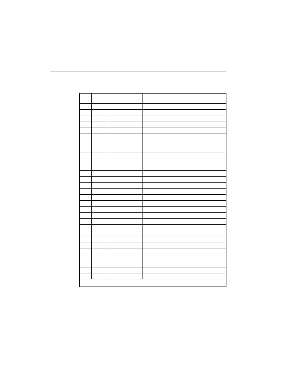
Table D-F
RS-530-to-V.35 Adapter Cable Pinouts
See Figure D-4.
P i n Name I n p u t / O u t p u t
D e s c r i p t i o n s
A
Shield
I / O
Shield for cable
B
SG
I / O
Signal Ground
C
RTS
I
Ready to Send
D
CTS
O
Clear to Send
E
DSR
O
Data Set Ready
F
CD
O
Carrier Detect
H
DTR
I
Data Terminal Ready
J *
RI
O
Ring Indicator
P
SD-A
I
Send Data
R
RD-A
O
Receive Data
S
SD-B
I
Send Data (return)
T
RD-B
O
Receive Data (return)
U
TC-A
I
External Transmit Clock
V
RC-A
O
Receive Clock
W
TC-B
I
External Transmit Clock
X
RC-B
O
Receive Clock (return)
Y
S T - A
O
Send Timing
A A
ST-B
O
Send Timing (return)
BB
NC
N / A
No Connection
CC
NC
N / A
No Connection
DD
NC
N / A
No Connection
EE
NC
N / A
No Connection
FF
NC
N / A
No Connection
HH
NC
N / A
No Connection
J J
NC
N / A
No Connection
KK
NC
N / A
No Connection
LL
NC
N / A
No Connection
MM
NC
N / A
No Connection
NN
NC
N / A
No Connection
*Pin J (ring indicator) is needed for most video conferencing applications.
- Express 4110 (205 pages)
- Gigabit Ethernet Multi-Mode Fiber Tributary Module 1184519L1 (2 pages)
- U-BR1TE ISDN 2B1Q (4 pages)
- DSU/CSU (6 pages)
- 3010 (30 pages)
- NetVanta 1024 (2 pages)
- FT1 (10 pages)
- IP Mini-DSLAM (2 pages)
- 6530 (2 pages)
- 6530 (20 pages)
- AHT1U (2 pages)
- DS3 MX (2 pages)
- 600R (264 pages)
- DUAL Nx56/64 1200142L1# (42 pages)
- NetVanta T1/FT1 + DSX-1 (2 pages)
- IQ SERIES 56 (1 page)
- 1200070L2 (187 pages)
- 1200051L2 (165 pages)
- NETVANTA 3120 (2 pages)
- 1200 (2 pages)
- NetVanta Series (2 pages)
- 850 (4 pages)
- ATLAS 800 Series Module QUAD E1 (2 pages)
- Atlas 830 (2 pages)
- TSU LT (2 pages)
- Express L1.5 (2 pages)
- MX2820-48 VDC M13 MUX (2 pages)
- Dial Backup Interface Module 1204006L2 (2 pages)
- 900 Series (2 pages)
- Atlas 550 (1 page)
- Atlas 550 (262 pages)
- NetVanta 5305 (2 pages)
- 1200350L1 (134 pages)
- ATM Mini-DSLAM (2 pages)
- D4-n x 64 DSU DP (4 pages)
- Type 400 (4 pages)
- 1204002L1 (163 pages)
- NetVanta ADSL (2 pages)
- 3000 HTU-C (2 pages)
- 600e (2 pages)
- 1200F (2 pages)
- D4 TRI-C DP (1 page)
- 239 T1 HDSL4 (20 pages)
- 3000 NTU-8 (18 pages)
- 1200130L1 (153 pages)