Appendix d pinouts – ADTRAN ISU 512 User Manual
Page 105
61202.086L1-1
ISU 512 User Manual
89
Appendix D
Pinouts
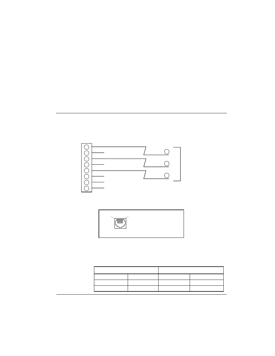
Figure D-1 illustrates the EIA-232 to DB-25 adapter connector. Figures D-2
through D-4 show the interfaces for the pinouts identified in Tables D-A
through D-F.
Figure D-1
EIA-232 to DB-25 Adapter Connector
Figure D-2
RJ-45 ISDN Line Interface
Table D-A
Pinouts for Chain In and Chain Out Ports
1
2
3
4
5
6
7
8
7
2
3
RS-232
DB Style
Connector
RS-232
ISDN
PIN 1
PIN 8
Pin 4
Ring
Pin 5
Tip
For U Interface:
For ST Interface:
Pin 3,6
Transmit pair
Pin 4,5
Receive pair
Chain In Port
Chain Out Port
Pin 1
Ground
Pin 1
Ground
Pin 3
Rx Data
Pin 3
Chain Rx Data
Pin 5
Tx Data
Pin 5
Chain Tx Data
See also other documents in the category ADTRAN Hardware:
- Express 4110 (205 pages)
- Gigabit Ethernet Multi-Mode Fiber Tributary Module 1184519L1 (2 pages)
- U-BR1TE ISDN 2B1Q (4 pages)
- DSU/CSU (6 pages)
- 3010 (30 pages)
- NetVanta 1024 (2 pages)
- FT1 (10 pages)
- IP Mini-DSLAM (2 pages)
- 6530 (20 pages)
- 6530 (2 pages)
- AHT1U (2 pages)
- DS3 MX (2 pages)
- 600R (264 pages)
- DUAL Nx56/64 1200142L1# (42 pages)
- NetVanta T1/FT1 + DSX-1 (2 pages)
- IQ SERIES 56 (1 page)
- 1200070L2 (187 pages)
- 1200051L2 (165 pages)
- NETVANTA 3120 (2 pages)
- 1200 (2 pages)
- NetVanta Series (2 pages)
- 850 (4 pages)
- ATLAS 800 Series Module QUAD E1 (2 pages)
- Atlas 830 (2 pages)
- TSU LT (2 pages)
- Express L1.5 (2 pages)
- MX2820-48 VDC M13 MUX (2 pages)
- Dial Backup Interface Module 1204006L2 (2 pages)
- 900 Series (2 pages)
- Atlas 550 (1 page)
- Atlas 550 (262 pages)
- NetVanta 5305 (2 pages)
- 1200350L1 (134 pages)
- ATM Mini-DSLAM (2 pages)
- D4-n x 64 DSU DP (4 pages)
- Type 400 (4 pages)
- 1204002L1 (163 pages)
- NetVanta ADSL (2 pages)
- 3000 HTU-C (2 pages)
- 600e (2 pages)
- 1200F (2 pages)
- D4 TRI-C DP (1 page)
- 239 T1 HDSL4 (20 pages)
- 3000 NTU-8 (18 pages)
- 1200130L1 (153 pages)