Spektrum SPMAR9310 User Manual
Page 6
10
11
EN
EN
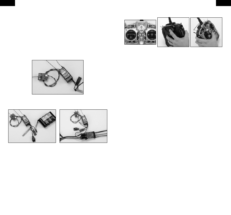
Step 5. Plugging in the Servo Leads
Plug the servo leads into the appropriate servo ports in the receiver noting the
polarity of the servo connector. Note that the signal wire (orange for JR servos)
faces toward the center of the receiver. Consult your radio’s manual for specific
detail as to which servo plugs connect into which servo port channel.
Step 6. Binding the Receiver
The AR9310 must be bound to the transmitter before it will operate. Binding is
the process of teaching the receiver the specific code of the transmitter so it
will only connect to that specific transmitter.
1. To bind an AR9310 to a DSM2/DSMX transmitter, insert the bind plug in
the BATT/BIND port on the receiver.
2. Power the receiver. The LED on the receiver should be flashing, indicating
that the receiver is in bind mode and ready to be bound to the transmitter.
When binding through an ESC, the
ESC’s lead must be plugged into the
port operating the motor, typically
the gear or AUX2 channel. The servo
monitor is helpful in determining
which channel is being used.
Shown using a separate receiver
pack. (Battery can be plugged into
any open port.)
3. Move the sticks and switches on the transmitter to the desired failsafe
positions (normally mid flap for dethermalizing).
4. Follow the procedures of your specific transmitter to enter Bind Mode, the
system will connect within a few seconds. Once connected, the LED on the
receiver will go solid indicating the system is connected.
5. Remove the bind plug from the BATT/BIND port on the receiver before you
power off the transmitter and store it in a convenient place
IMPORTANT: Remove the bind plug to prevent the system from entering bind
mode the next time the power is turned on.
Step 7. Radio Setup and Programming
Following the instructions in your radio manual, program your airplane.
Step 8. Rebinding the Receiver
After you’ve programmed your model, it’s important to rebind the system so the
true failsafe control surface positions are set.
Step 9. Ground Range Testing and Verification with Flight Log
Advanced Range Testing Using a Flight Log
In airplanes that have significant carbon fiber construction it is imperative to
first do a ground range check using a flight log. This ground range check will
confirm that the internal and remote receivers are operating optimally and
that the antennas are properly mounted in a position that will give positive
RF coverage in all attitudes. This Advanced Range Check allows the RF
performance of each receiver and the positions of each antenna to be verified
and to optimize the locations of the antennas.
Advanced Range Test
1. Plug a Flight Log (SPM9540) into the data port in the AR9310. If the port
is being used for the battery, a Y-harness can be used or plug the battery
into any other unused port.
2. Turn on the system (Tx and Rx).
3. Advance the Flight Log until F- frame losses are displayed by pressing the
button on the Flight Log.
4. Have a helper hold your aircraft while observing the Flight Log data.
5. Standing 30 paces away from the model, face the model with the
transmitter in your normal flying position and put your transmitter into
range test mode. This causes reduced power output from the transmitter.
6. Have your helper position the model covering all orientations (nose up,
nose down, nose toward the Tx, nose away from the Tx, etc.) while your