Spektrum SPMAR9310 User Manual
Page 5
8
9
EN
EN
A. Full Carbon
External
antennas
Internal
antennas
External
antennas
Internal
antennas
Optional
location
Full Carbon
2.4GHz Friendly
Fuselage with Carbon
Wing
2.4GHz Friendly
Fuselage with Molded
Non-Carbon Wing
All components of the airplane
including the entire fuselage, the wing
and tail are constructed of carbon
fiber or have a carbon fiber weave
throughout the aircraft.
This type of aircraft will require that all
antennas be installed externally.
B. 2.4GHz Friendly Fuselage with
Carbon Wing
The section forward of the wing
is constructed of non-conductive
materials like fiberglass, Kevlar, etc.
but the wing and possibly the tail
section have carbon or carbon weave
construction.
Antennas in the nose of this type of
aircraft can be installed internally while
an antenna installed behind the wing
must be mounted externally.
C. 2.4GHz Friendly Fuselage with
Molded Non-Carbon Wing
The section forward of the wing and
the wing itself is constructed of non-
conductive materials like fiberglass,
Kevlar, etc. The wing may, however,
contain a carbon spar, which is an
insignificant volume of carbon to have
an effect. The tail section can be either
carbon, carbon weave or fiberglass
construction.
All antenna can be mounted internally forward of the wing in this type of
aircraft.
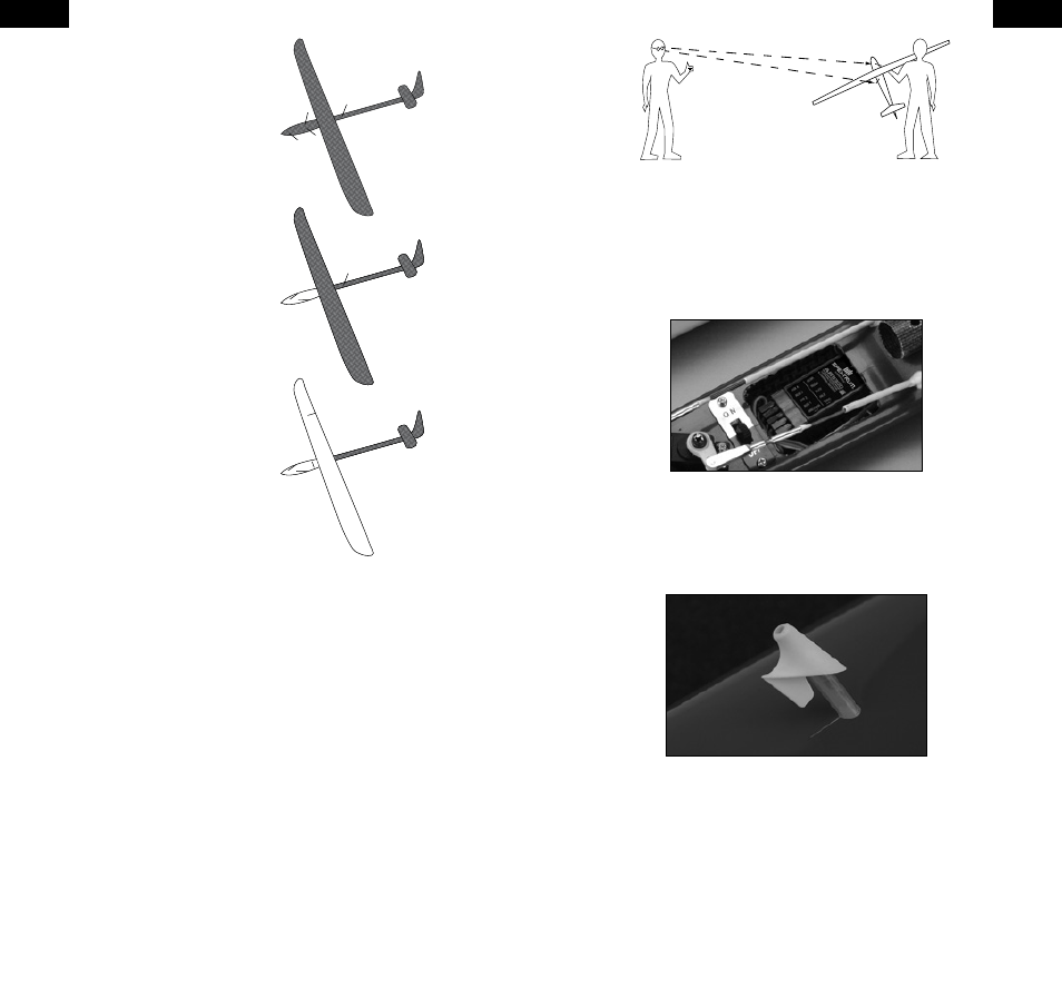
Step 2. Determining Antenna Mounting Positions
After determining the type of aircraft from the list above, use the above
illustrations as a guideline as to where the feeder antennas should be mounted.
The goal is to mount the antennas in a location such that at least two will
always be in the RF visual line of sight of the transmitter (i.e. not blocked by
carbon fiber structures) in all attitudes. This can easily be visualized by having
a helper stand about 20 feet away and rotate the airplane in all attitudes
confirming that in all positions there is a direct line between you and at least
two receiver antennas that aren’t blocked by carbon fiber structure.
If you have a full carbon sailplane, it is highly recommended that an optional
fourth receiver with feeder antenna be installed. Carbon Fuselage Remote
(SPM9546)
Step 3. Installing the Receivers
Install the Main receiver in the normal position recommended by the airplanes’
manufacturer, noting that the data/bind port should be easily accessible as a
flight log will be used to confirm RF link performance. Double-sided tape or
foam can be used to secure the main receiver in place. Using double-sided
servo tape mount the remote receiver(s) within 3 inches from where you intend
on having the antennas exit the fuselage.
Step 4. Mounting the Antennas
Three 2.4GHz Antenna Exit Guides (SPM6824) antenna mounts (with tubes) are
included to make external mounting easy. To install the antenna mount, drill a
1/8-inch hole in the desired antenna mounting position; then, using a hobby
knife slot the hole as shown.
Insert the tube in the mount; then using medium CA, glue the mount and tube
in place in the fuselage. Trim the tube to length inside the fuselage if necessary.
Now slide the feeder antenna through the tube until the 31mm tip completely
exits the mount. Using a drop of CA, glue the antenna to the mount making
sure that the 31mm active portion of the antenna tip is fully exposed.
If the antenna is to be mounted internally (in the front of a 2.4GHz friendly
fuselage) the coax can be taped into position. Be sure the 31mm tip is located
at least 2 inches from any significant carbon structure and from the battery.