Apogee™ xtl waterblock installation, Electrical installation, Adjustable pump speed – Swiftech H20 X20 EDGE SERIES User Manual
Page 12
Copyright Swiftech 2010
– All rights reserved – Last revision date: 8-17-10 - Information subject to change without notice – URL
Rouchon Industries, Inc., dba Swiftech
– 151 West Victoria Street, Long Beach, CA 90805 – Tel. 310-763-0336 – Fax 310-763-7095 - E Mail: [email protected]
12 of 16
c.
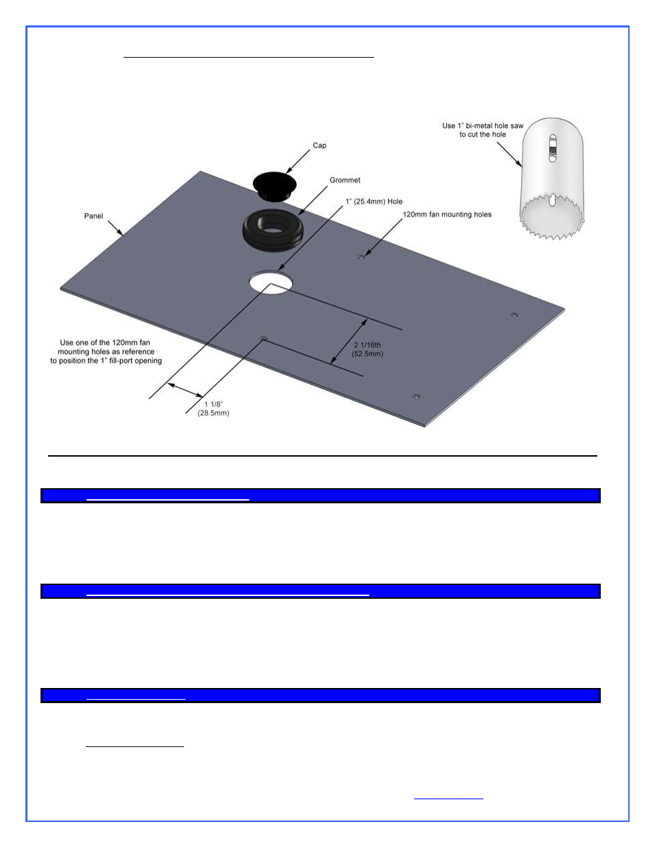
Optional external panel fill-port (horizontal installations only)
A rubber grommet and a plastic cap are provided with your kit to allow you to create a convenient and clean opening in the upper case
panel so you may access the fill-
port for coolant refills at any time. In order to cut the hole, please use a 1” (25mm) bi-metal hole saw.
Center the hole using one of the adjoining 120mm fan holes as reference, as shown below (3D illustrations also provided in the
installation CD):
2.
A
POGEE
™
XTL
WATERBLOCK INSTALLATION
Please refer to the separate installation guide included inside of the waterblock box. Removal of the motherboard is generally
necessary to install the water-block back-plate.
Once the
APOGEE™ waterblock securely fastened to the motherboard, go-ahead and install the motherboard into the chassis,
following the instructions provided in your motherboard installation guide.
3.
C
ONNECTING THE TUBES BETWEEN
MCR
D
RIVE AND
A
POGEE
™
WATERBLOCK
For tube routing, simply follow the 3D model that corresponds to your own installation. Always avoid tight radii in the tubing to prevent it from
kinking. Whenever you encounter a tight spot disallowing sufficient radius in the tube, then use an aftermarket elbow. Please note that excessive
use of elbows in a loop creates substantial pressure drop in the coolant flow, and may affect the performance of your system. Use them
sparingly! With regards to after-market fittings, both the Apogee Water-block and the MCR Drive Radiators are compatible with the
G ¼”
standard. Once all the tubes are connected, use the provided hose clamps to secure the tubes to the hose barbs.
4.
E
LECTRICAL
I
NSTALLATION
Please follow the diagrams below for connecting the components to the motherboard and power supply.
A. Adjustable Pump Speed