Allied Telesis AT-8350GB User Manual
Page 33
AT-8350GB Installation Guide
33
Table 8 lists the AT-RPS2004 power supply LEDs.
Type of Connector
The RPS2001 and RPS2004 power supply units feature the 8-pin
connector which connects to the back panel of the AT-8350 GB switch.
The tables below list the 8-pin DIN male and female connector pins and
definitions.
Table 9 lists the 8-pin DIN male connector pins and definitions.
Table 8 AT-RPS2004 Power Supply LEDs
LED
State
Description
Power Status
RPS
Flashing Green
RPS power is on standby.
Green
RPS power is ON and switch is connected
to it.
Red
RPS power failed.
Fan Status
FAN
Green
Fan power is ON.
Red
Fan power failed.
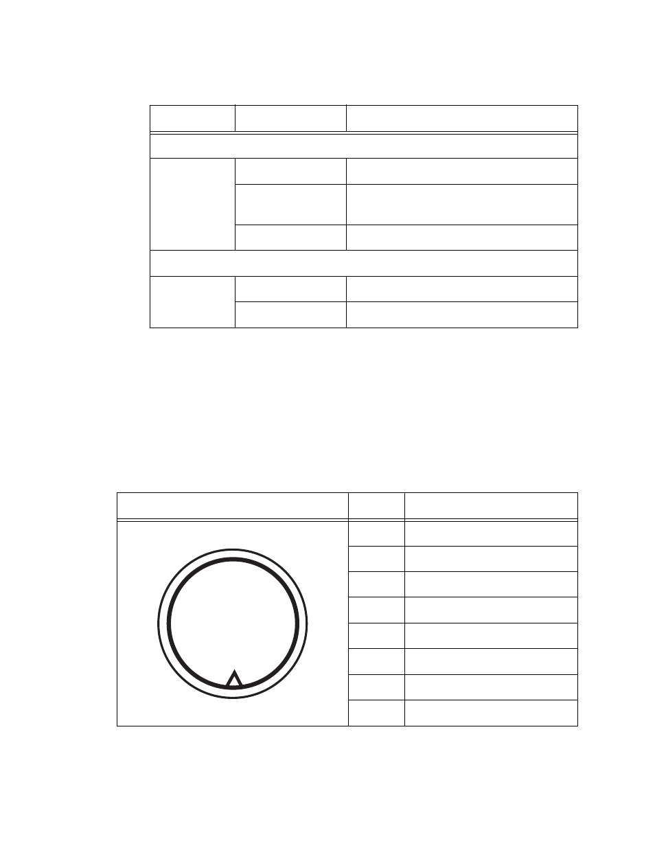
Table 9 Pin Definition of the 8-pin DIN Male Connector (switch side)
Male 8-pin DIN Connector
Pin
Definition
1
GND
2
RPS_Present
3
12 volts
4
12 volts
5
12 volts
6
SW_Present
7
GND
8
GND
(1)
(2)
(3)
(4)
(5)
(7)
(6)
(8)
MALE
- AT-GS908M (54 pages)
- AT-x230-10GP (80 pages)
- AT-GS950/48PS (64 pages)
- AT-GS950/10PS (386 pages)
- AT-GS950/16PS (386 pages)
- AT-GS950/48PS (386 pages)
- AT-9000 Series (258 pages)
- AT-9000 Series (1480 pages)
- IE200 Series (70 pages)
- AT-GS950/48 (410 pages)
- AT-GS950/8 (52 pages)
- AT-GS950/48 (378 pages)
- AT-GS950/48 (60 pages)
- SwitchBlade x8106 (322 pages)
- SwitchBlade x8112 (322 pages)
- SwitchBlade x8106 (240 pages)
- SwitchBlade x8112 (240 pages)
- AT-TQ Series (172 pages)
- AlliedWare Plus Operating System Version 5.4.4C (x310-26FT,x310-26FP,x310-50FT,x310-50FP) (2220 pages)
- FS970M Series (106 pages)
- 8100L Series (116 pages)
- 8100S Series (140 pages)
- x310 Series (116 pages)
- x310 Series (120 pages)
- AT-GS950/24 (404 pages)
- AT-GS950/24 (366 pages)
- AT-GS950/16 (44 pages)
- AT-GS950/16 (404 pages)
- AT-GS950/16 (364 pages)
- AT-GS950/8 (52 pages)
- AT-GS950/8 (404 pages)
- AT-GS950/8 (364 pages)
- AT-8100 Series (330 pages)
- AT-8100 Series (1962 pages)
- AT-FS970M Series (330 pages)
- AT-FS970M Series (1938 pages)
- SwitchBlade x3106 (288 pages)
- SwitchBlade x3112 (294 pages)
- SwitchBlade x3106 (260 pages)
- SwitchBlade x3112 (222 pages)
- AT-S95 CLI (AT-8000GS Series) (397 pages)
- AT-S94 CLI (AT-8000S Series) (402 pages)
- AT-IMC1000T/SFP (23 pages)
- AT-IMC1000TP/SFP (24 pages)
- AT-SBx3106WMB (44 pages)