Gigabit connector leds, Figure 12: gigabit connector leds – Allied Telesis AT-8350GB User Manual
Page 27
AT-8350GB Installation Guide
27
Gigabit
Connector LEDs
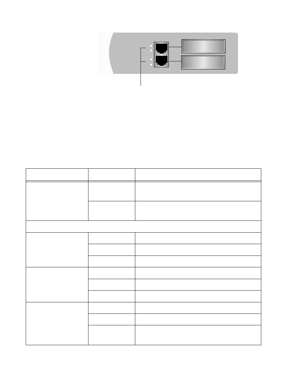
Figure 12 Gigabit Connector LEDs
Ports 49 and 50 each have two LEDs. The S (Selection) LED indicates
which port, the twisted pair port or a GBIC port, has been activated in the
management software. The M (Mode) LED indicates the operating
characteristics of the port, such as speed and duplex mode.
Table 6 describes the 10/100/1000 Mbps port LEDs.
Connector LEDs
49
50
S
M
S
M
Table 6 10/100/1000 Mbps Port LEDs
LED
State
Description
S (Selection)
Steady Green
The twisted pair port has been activated in the
management software as the active port.
Amber
The GBIC port has been activated in the
management software as the active port.
M (Mode)
LINK
Flashing Green
A link with activity
.
Steady Green
A link with no activity.
OFF
No link has been established.
100
Amber
A 1000 Mbps link has been established.
Green
A 100 Mbps link has been established.
OFF
A 10 Mbps link has been established.
FULL
Green
The port is in full-duplex mode.
Flashing Green
The port is in half-duplex mode with collisions.
OFF
The port is in half-duplex mode and no data colli-
sions are occurring on the port.