Front and rear panels, Figure 1: front panel figure 2: rear panel – Allied Telesis AT-TQ2450 User Manual
Page 19
AT-TQ2450 Wireless Access Point Installation Guide
19
Front and Rear Panels
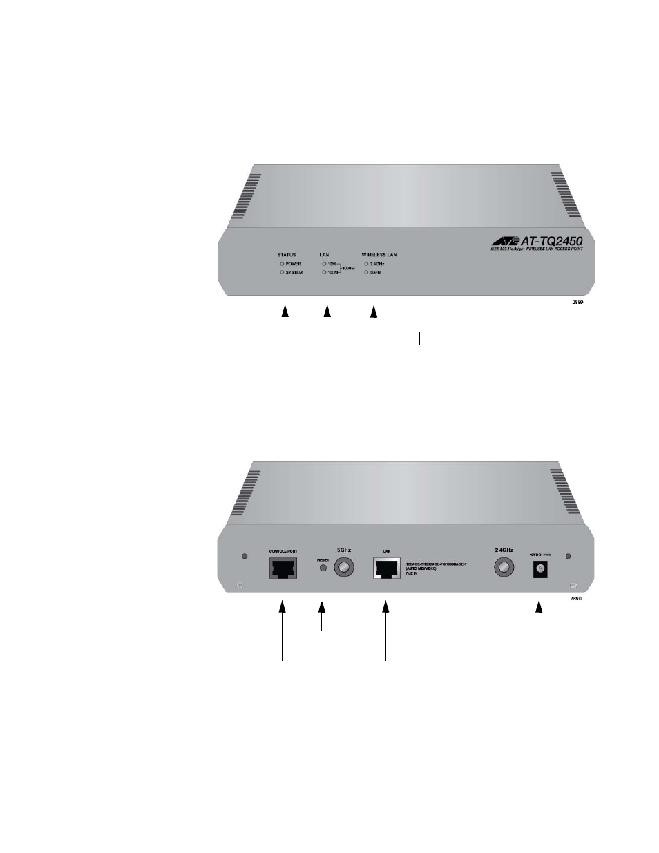
The front and rear panels of the unit are illustrated in Figure 1 and
Figure 2.
Figure 1. Front Panel
The LEDs are described in “LEDs” on page 24.
Figure 2. Rear Panel
The rear panel components are listed in Table 1 on page 20.
Radio
LEDs
LAN Port
LEDs
Power and
System Status
LEDs
Reset Button
Console Port
LAN Port
DC Power Connector
See also other documents in the category Allied Telesis Computer hardware:
- AT-GS908M (54 pages)
- AT-x230-10GP (80 pages)
- AT-GS950/48PS (64 pages)
- AT-GS950/10PS (386 pages)
- AT-GS950/16PS (386 pages)
- AT-GS950/48PS (386 pages)
- AT-9000 Series (258 pages)
- AT-9000 Series (1480 pages)
- IE200 Series (70 pages)
- AT-GS950/8 (52 pages)
- AT-GS950/48 (378 pages)
- AT-GS950/48 (60 pages)
- AT-GS950/48 (410 pages)
- SwitchBlade x8106 (322 pages)
- SwitchBlade x8112 (322 pages)
- SwitchBlade x8106 (240 pages)
- SwitchBlade x8112 (240 pages)
- AT-TQ Series (172 pages)
- AlliedWare Plus Operating System Version 5.4.4C (x310-26FT,x310-26FP,x310-50FT,x310-50FP) (2220 pages)
- FS970M Series (106 pages)
- 8100S Series (140 pages)
- 8100L Series (116 pages)
- x310 Series (116 pages)
- x310 Series (120 pages)
- AT-GS950/24 (366 pages)
- AT-GS950/16 (44 pages)
- AT-GS950/24 (404 pages)
- AT-GS950/16 (404 pages)
- AT-GS950/16 (364 pages)
- AT-GS950/8 (404 pages)
- AT-GS950/8 (364 pages)
- AT-GS950/8 (52 pages)
- AT-8100 Series (330 pages)
- AT-8100 Series (1962 pages)
- AT-FS970M Series (1938 pages)
- AT-FS970M Series (330 pages)
- SwitchBlade x3106 (288 pages)
- SwitchBlade x3112 (294 pages)
- SwitchBlade x3106 (260 pages)
- SwitchBlade x3112 (222 pages)
- AT-S95 CLI (AT-8000GS Series) (397 pages)
- AT-S94 CLI (AT-8000S Series) (402 pages)
- AT-IMC1000T/SFP (23 pages)
- AT-IMC1000TP/SFP (24 pages)
- AT-SBx3106WMB (44 pages)