Dc terminal block, Stripped wire – Allied Telesis 8100S Series User Manual
Page 92
Chapter 5: Powering On the Switch
92
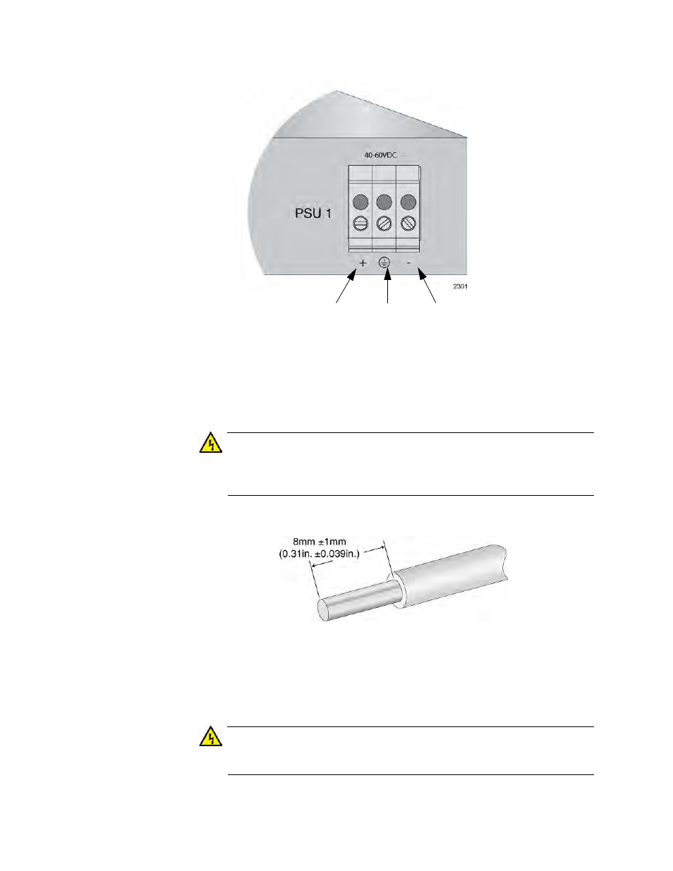
Figure 37. DC Terminal Block
3. With a 14-gauge wire-stripping tool, strip the three wires in the tray
cable coming from the DC input power source to 8mm
± 1mm (0.31 in.,
± 0.039 in.), as shown in Figure 38 on page 92.
Warning
Do not strip more than the recommended amount of wire. Stripping
more than the recommended amount can create a safety hazard by
leaving exposed wire on the terminal block after installation.
E10
Figure 38.
Stripped Wire
4. Insert the power supply ground wire into the middle connector of the
DC terminal and tighten the connection with a flathead screwdriver, as
shown in Figure 39 on page 93.
Warning
When installing this equipment, always ensure that the power supply
ground connection is installed first and disconnected last.
E11
Positive
Ground
Negative
Terminal
Terminal
Terminal