Stacking port pinouts, Stacking port pin layout (front view), Stacking port pin signals – Allied Telesis 8100S Series User Manual
Page 116
Appendix A: Technical Specifications
116
Stacking Port Pinouts
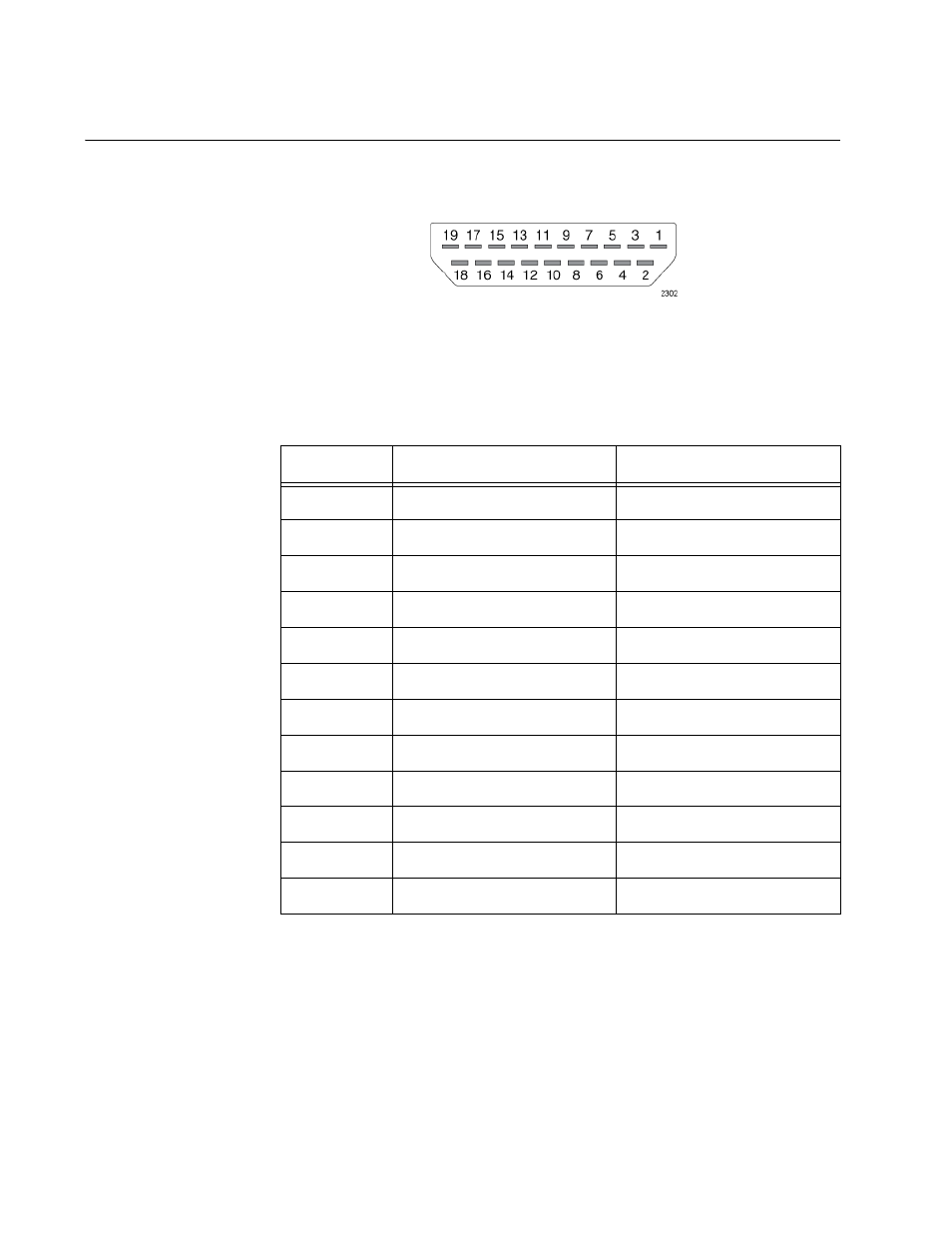
Figure 46 illustrates the pin layout of the S1 and S2 stacking ports.
Figure 46. Stacking Port Pin Layout (Front View)
Table 30 lists the pin signals of the stacking ports.
Table 30. Stacking Port Pin Signals
Pin
S1 Port
S2 Port
1
Not connected
Not connected
2
Ground
Ground
3
Not connected
Not connected
4
Transmit data1+
Receive data1+
5
Ground
Ground
6
Transmit data1-
Receive data1-
7
Receive data0+
Transmit data0+
8
Ground
Ground
9
Receive data0-
Transmit data0-
10
Not connected
Not connected
11
Ground
Ground
12 to 19
Not connected
Not connected
This manual is related to the following products: