Rj-45 twisted pair port pinouts, Rj-45 socket pin layout (front view), Pin signals for 10 and 100 mbps – Allied Telesis 8100S Series User Manual
Page 112: Pin signals for 1000 mbps
Appendix A: Technical Specifications
112
RJ-45 Twisted Pair Port Pinouts
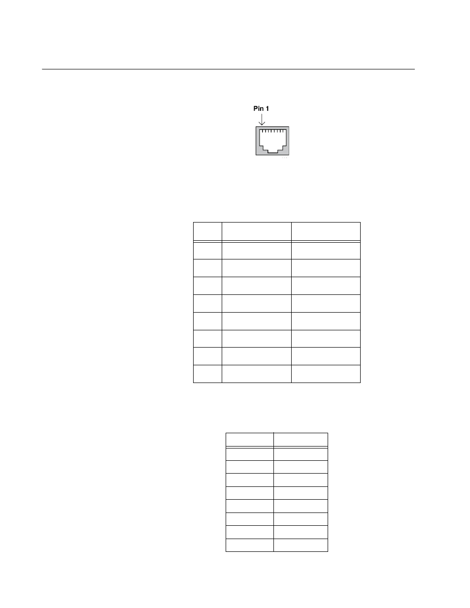
Figure 45 illustrates the pin layout of the RJ-45 connectors and ports.
Figure 45. RJ-45 Socket Pin Layout (Front View)
Table 25 lists the pin signals for 10 and 100 Mbps.
Table 26 lists the pin signals when a port operating at 1000 Mbps.
Table 25. Pin Signals for 10 and 100 Mbps
Pin
MDI Signal
MDI-X Signal
1
TX+
RX+
2
TX-
RX-
3
RX+
TX+
4
Not used
Not used
5
Not used
Not used
6
RX-
TX-
7
Not used
Not used
8
Not used
Not used
Table 26. Pin Signals for 1000 Mbps
Pinout
Pair
1
Pair 1 +
2
Pair 1 -
3
Pair 2 +
4
Pair 3 +
5
Pair 3 -
6
Pair 2 -
7
Pair 4 +
8
Pair 4 -
This manual is related to the following products: