8100s series switches, Components of the 8100s series switches – Allied Telesis 8100S Series User Manual
Page 66
Chapter 2: Beginning the Installation
66
8100S Series
Switches
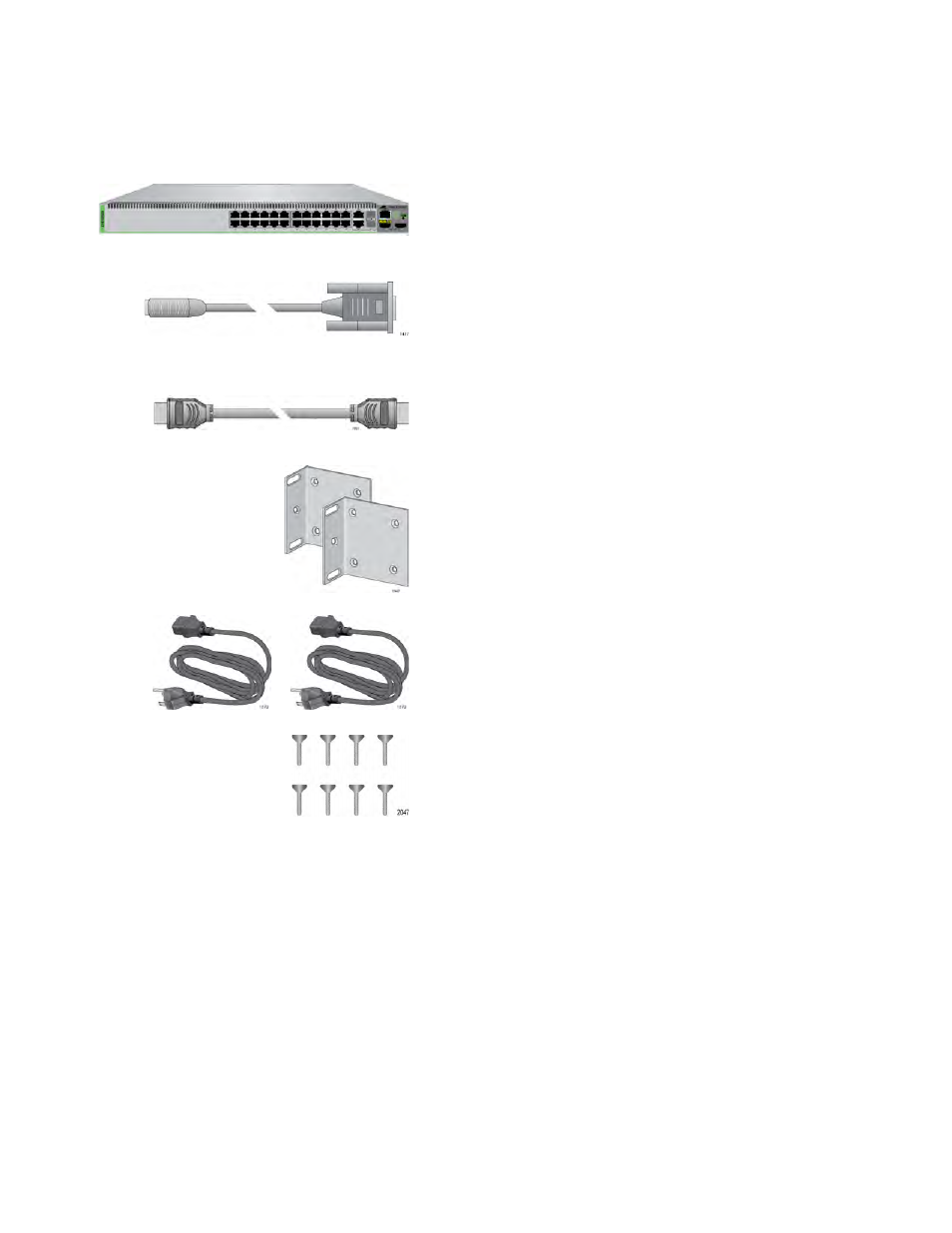
The 8100S Series switches, except the AT-8100S/24C Switch, come with
the components listed in Figure 20.
Figure 20. Components of the 8100S Series Switches
One 8100S Series switch
Two rack mounting brackets
One 2 m (6.6 ft) local management cable with
RJ-45 (8P8C) and DB-9 (D-sub 9-pin)
connectors.
Eight bracket screws
Two regional AC power cords
(Not included with DC
powered switches.)
One 1 m (3.3 ft) stacking cable with two type A
HDMI connectors.
This manual is related to the following products:
See also other documents in the category Allied Telesis Computer hardware:
- AT-GS908M (54 pages)
- AT-x230-10GP (80 pages)
- AT-GS950/48PS (64 pages)
- AT-GS950/10PS (386 pages)
- AT-GS950/16PS (386 pages)
- AT-GS950/48PS (386 pages)
- AT-9000 Series (258 pages)
- AT-9000 Series (1480 pages)
- IE200 Series (70 pages)
- AT-GS950/48 (378 pages)
- AT-GS950/48 (60 pages)
- AT-GS950/48 (410 pages)
- AT-GS950/8 (52 pages)
- SwitchBlade x8106 (322 pages)
- SwitchBlade x8112 (322 pages)
- SwitchBlade x8106 (240 pages)
- SwitchBlade x8112 (240 pages)
- AT-TQ Series (172 pages)
- AlliedWare Plus Operating System Version 5.4.4C (x310-26FT,x310-26FP,x310-50FT,x310-50FP) (2220 pages)
- FS970M Series (106 pages)
- 8100S Series (140 pages)
- x310 Series (116 pages)
- x310 Series (120 pages)
- AT-GS950/16 (44 pages)
- AT-GS950/24 (404 pages)
- AT-GS950/24 (366 pages)
- AT-GS950/16 (404 pages)
- AT-GS950/16 (364 pages)
- AT-GS950/8 (404 pages)
- AT-GS950/8 (364 pages)
- AT-GS950/8 (52 pages)
- AT-8100 Series (330 pages)
- AT-8100 Series (1962 pages)
- AT-FS970M Series (330 pages)
- AT-FS970M Series (1938 pages)
- SwitchBlade x3106 (288 pages)
- SwitchBlade x3112 (294 pages)
- SwitchBlade x3106 (260 pages)
- SwitchBlade x3112 (222 pages)
- AT-S95 CLI (AT-8000GS Series) (397 pages)
- AT-S94 CLI (AT-8000S Series) (402 pages)
- AT-IMC1000T/SFP (23 pages)
- AT-IMC1000TP/SFP (24 pages)
- AT-SBx3106WMB (44 pages)