ROHM ZG/ZS, ZGU/ZSU, EG/ES - Geared scroll chucks User Manual
Page 14
Max. permissible speed for la-
the chucks ZG-ZS, ZGU-ZSU
and ZG Hi-Tru in accordance
with DIN 6350
The maximum permissible speed
is defined so that at maximum
gripping force and when using the
heaviest jaws, a reserve of 1/3 of
the total available gripping force
remains. The jaws may not pro-
ject over the outside diameter of
the chuck. Lathe chucks must be
in flawless condition.
In the case of cast lathe chucks,
the maximum permissible speed
is coordinated to the permissible
peripheral speed for cast iron.
Otherwise, the stipulations of DIN
6281 Part 1 are applicable.
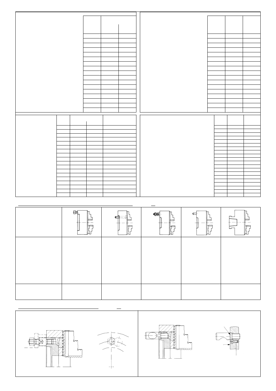
2. Mounting the lathe chuck on the machine spindle head (valid for all chuck types and independent chucks)
Size
3 and 4-jaw chucks
Cast iron
Steel
body
body
74
5000
--
80
5000
7000
100
4500
6300
125
4000
5500
140
3700
5000
160
3600
4600
200
3000
4000
250
2500
3000
315
2000
2300
350
1700
1900
400
1600
1800
500
1000
1300
630
800
850
700
650
800
800
600
700
1000
480
560
1250
380
450
Gripping force for 3-jaw lathe
chucks ZG-ZS, ZGU-ZSU and
ZG Hi-Tru in accordance with
DIN 6350 and EG/ES in accor-
dance with DIN 6351
The gripping force is the sum of all
jaw forces acting radially on the
workpiece at standstill. The speci-
fied gripping forces are guideline
values. They apply to chucks in
flawless condition which are lubri-
cated with grease F80.
Size
Torque
Total
at the
gripping
wrench
force
in Nm
in KN
Machine spindle
DIN 800
DIN 55026,
DIN 55027
DIN 55029
ASA B 5.9
ASA B 5.9
DIN 55022 and
ASA B 5.9
Long taper
A1/A2 metr.
ISO 702/III
D 1 and
and ISO 702/I
ISO 702/II
Fixture
With stud and
Camlock stud
Fixture with
from the front
locknut
union nut
(DIN 55021 with
Cylindrical
stud bolt and nut)
centring rim
type A
Mounting
Fixture
With adapter plate
Short taper
Short taper
Short taper
Long taper
direct mounting
direct mounting
direct mounting
direct mounting
Max. permissible
speed for lathe
chuck EG-ES in
accordance with
DIN 6351
The specified va-
lues are only appli-
cable for workpie-
ces not exceeding
a specific unba-
lance of 25 gmm/
kg.
2.1 Mounting the chuck fixture elements (valid for all chuck types and independent chucks)
Short taper mounting with stud and locknut as per DIN 55027/22
Short taper mounting with camlock ASA B 5.9 D1 and DIN 55029
Note: The camlock stud must be screwed in until the face of the short taper is located
within the marking groove of the camlock stud, and the position of the fixing groove
is in agreement with the threaded hole. Screw in the cheese-head screw as far as
it will go.
Size
Cast body Iron body
3 and 4-jaw chucks
Max. permissible speed for face
plates type UGE-UGU-USE-USU
The specified values are only applica-
ble for workpiece not exceeding a
specific unbalance of 25 gmm/kg.
Size
Cast body Steel body
UGE-UGU USE-USU
74
30
11
80
30
13
100
60
27
125
80
31
140
90
40
160
110
47
200
140
55
250
150
63
315
180
69
350
210
74
400
240
92
500
260
100
630
280
105
700
280
105
800
300
110
1000
450
115
1250
450
115
150
1910
--
200
1430
3000
260
1150
2350
310
960
1970
350
820
1750
400
720
1530
450
640
1360
500
570
1220
560
520
1090
600
470
1020
630
430
970
710
400
860
800
350
765
900
310
680
1000
280
610
1100
260
555
1200
230
510
1300
220
470
1400
200
440
1500
190
410
Marking groove
Face
Cheese-head screw
100
2700
--
125
2400
--
160
2000
3000
200
1600
2450
250
1300
2000
315
900
1350
400
800
1250
500
630
800
630
510
700
14