Horner APG SmartStix HE559MIX577 User Manual
Page 6
Page 6
07 APR 2006
MIX577
Bits 9 through 12 of the 5th configuration word control the behavior of the analog outputs when network
communication is lost. The bit to channel correspondence is the same as for the mode and scale bits. If
the corresponding bit is set, the outputs hold the last state. If the corresponding bit is cleared, the outputs
are set to the respective value supplied to the HE550MIX577 in the second four words of the Consumed
Directed Analog Data sent by the OCS. The other bits of the 5th configuration word are unused.
Refer to SmartStix Analog Programming Guide.
6
INPUT AND OUTPUT CONVERSION FACTORS
The following table describes how real-world values are scaled in the controller. For a given physical
voltage or current, the register data value may be calculated by using the conversion factor from the
table. The following formula is used: Data = Voltage or Current / Conversion Factor
Example:
The user selects a voltage range of ±10V:
1.
The physical voltage is 6 Volts.
2.
Using the table, the conversion factor for the voltage range of ±10V is .0003125.
3.
To determine the data value, the formula is used: Data = V / Conversion Factor
19200 = 6 VDC / 0.0003125
4.
For the 4 to 20mA range, the offset, 4mA, must first be subtracted from the physical output value
before dividing by the scale factor to yield the register data value.
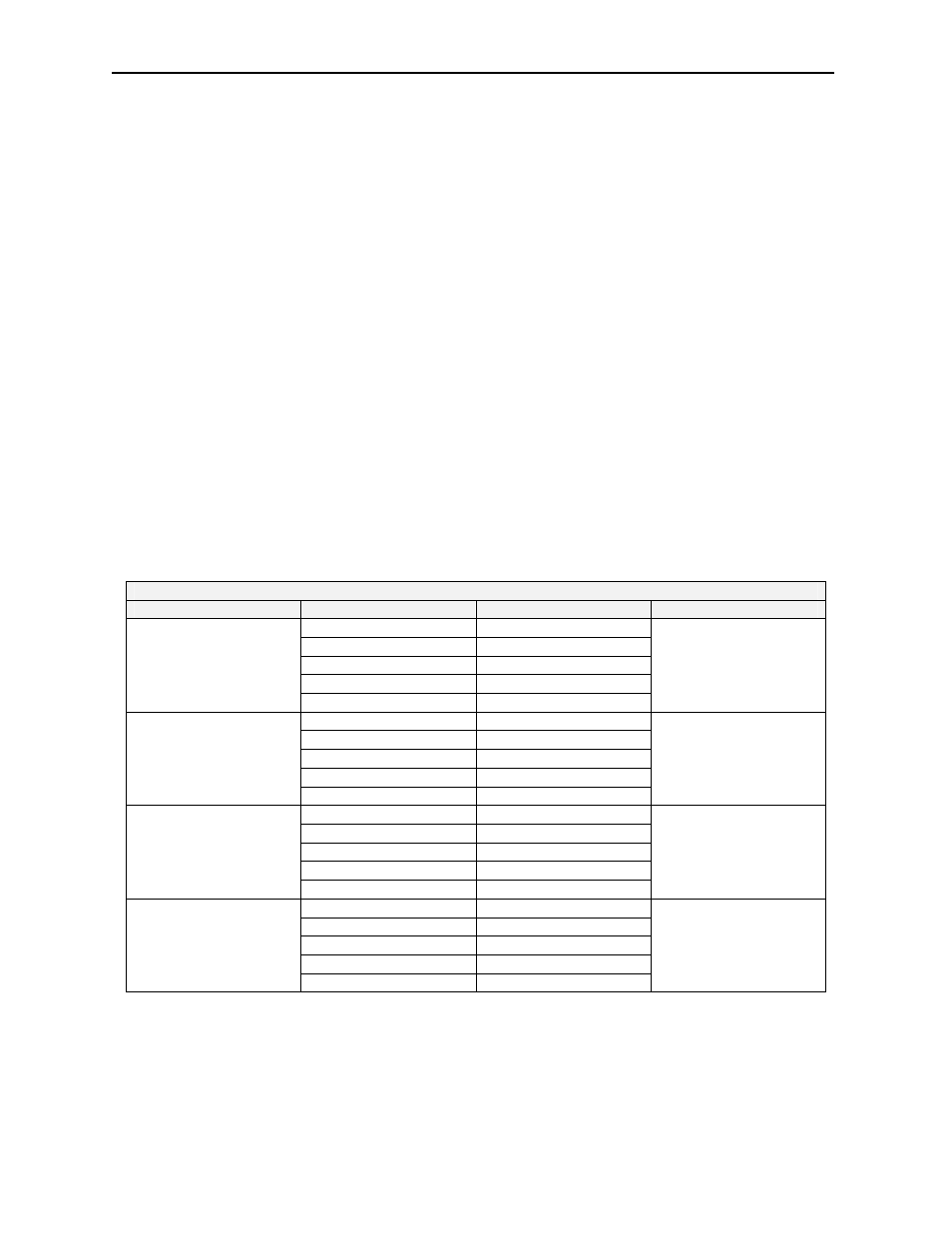
Conversion between Physical Values and Register Values
Selected Range
Volts / mA
Register Data
Conversion Factor
> +5.11
32767
+5.00 32000
0.00 0
-5.00 -32000
±5.00 V
< -5.11
-32768
0.00015625
> +10.23
32767
+10.00 32000
0.00 0
-10.00 -32000
±10.00 V
< -10.23
-32768
0.0003125
< +20.37
32767
+20.00 32000
+4.00 0
-12.00 -32000
4..20 mA
> -12.38
-32768
0.0005
> +20.47
32767
+20.00 32000
0 0
-20.00 -32000
±20.00 mA
< -20.47
-32768
0.0006250