10 installation / safety – Horner APG SmartStix HE559MIX577 User Manual
Page 10
Page 10
07 APR 2006
MIX577
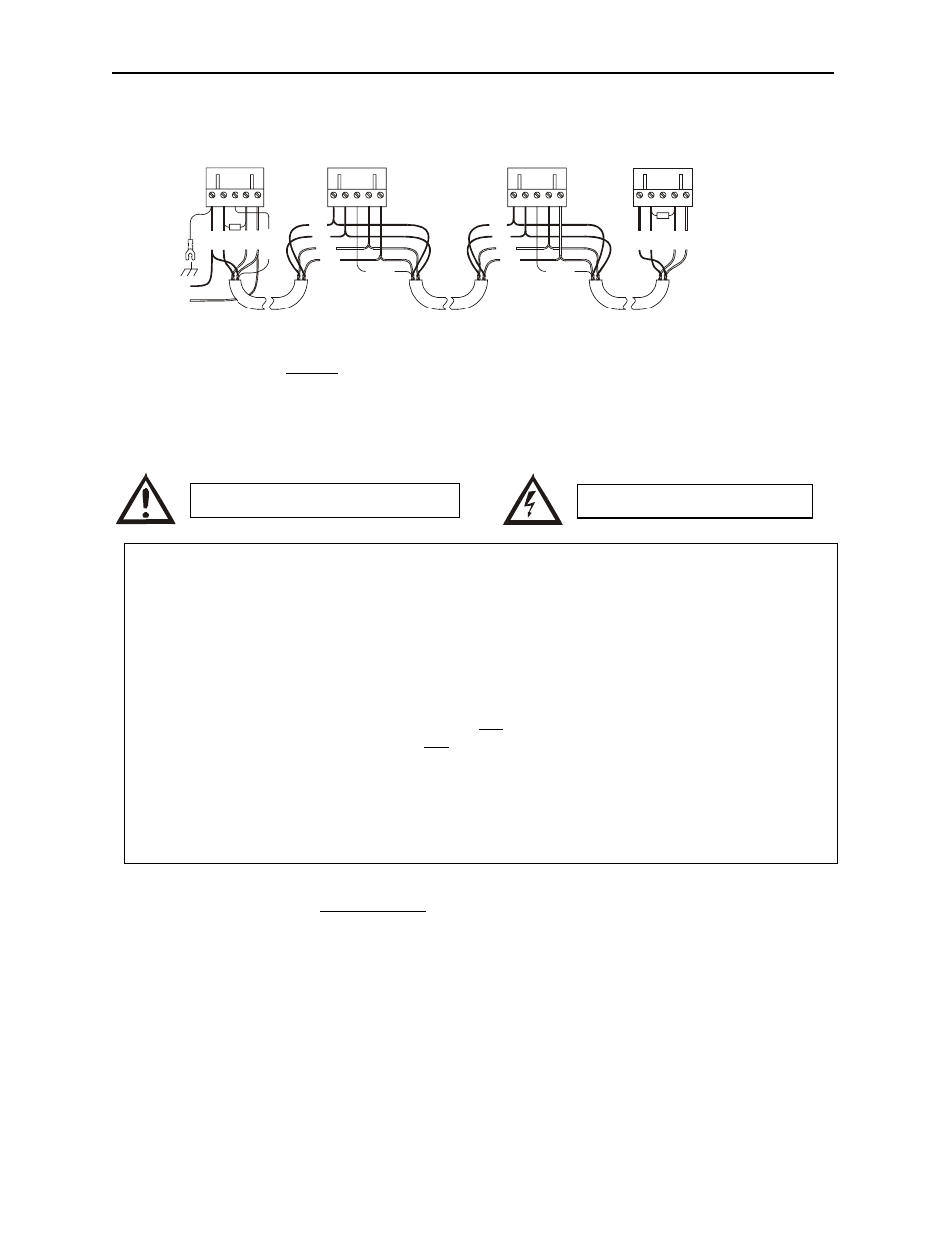
CAN Wiring
Note: 12 - 24VDC must be supplied to the network.
10
INSTALLATION / SAFETY
When found on the product, the following symbols specify:
For detailed installation and a handy checklist that covers panel box layout requirements and minimum
clearances, refer to the hardware manual of the controller you are using. (See the Additional
References section in this document.)
• All applicable codes and standards need to be followed in the installation of this product.
• For I/O wiring (discrete), use the following wire type or equivalent: Belden 8441 or equivalent.
RED
WHT
SHIELD
BLU
BLK
RE
D
SH
IE
LD
RED
WHT
BLU
BLK
V+
CN
_
L
V-
SH
IE
LD
12
1
Ω
CN
_
H
V+
CN
_
L
V-
SH
IE
LD
CN
_
H
RE
D
WHT
BL
U
BL
K
12
1
Ω
V+
CN
_
L
V-
SH
IE
LD
CN
_
H
RE
D
WHT
BL
U
BL
K
RED
WHT
SHIELD
BLU
BLK
RED
WHT
BLU
BLK
V+
CN
_
L
V-
SH
IE
LD
CN
_
H
12-25VDC
+
-
001CAN002
Warning: Consult user documentation.
Warning: Electrical Shock Hazard.
WARNING: To avoid the risk of electric shock or burns, always connect the safety (or earth)
ground before making any other connections.
WARNING: To reduce the risk of fire, electrical shock, or physical injury it is strongly
recommended to fuse the voltage measurement inputs. Be sure to locate fuses as close to the
source as possible.
WARNING: Replace fuse with the same type and rating to provide protection against risk of
fire and shock hazards.
WARNING: In the event of repeated failure, do not replace the fuse again as a repeated failure
indicates a defective condition that will not clear by replacing the fuse.
WARNING: Only qualified electrical personnel familiar with the construction and operation of
this equipment and the hazards involved should install, adjust, operate, or service this
equipment. Read and understand this manual and other applicable manuals in their entirety
before proceeding. Failure to observe this precaution could result in severe bodily injury or
loss of life.