A. diagnostic led indicators, B. status led indicators – Horner APG SmartStix HE559ADC970 User Manual
Page 9
ADC970
20 NOV 2003
Page 9
8
LEDS
SmartStix I/O Modules provide diagnostic and status LED indicators.
a. Diagnostic LED Indicators
Diagnostic LED
State
Meaning
Solid Red
RAM or ROM test failed
Blinking Red
I/O test failed
Blinking Green
Module is in power-up state
MS
(indicates fault status
of the Module )
Solid Green
Module is running n ormally
Solid Red
Network Ack or Dup ID test failed
Blinking Red
Network ID test failed
Blinking Green
Module is in Life Expectancy default state
NS
(indicates fault status
of the Network)
Solid Green
Network is running normally
b. Status LED Indicators
The Power Status LED illuminates Red when power is applied to the module. There are I/O Status LED
indicators for each of the Digital I/O points, which illuminate Red when an I/O point is ON.
9
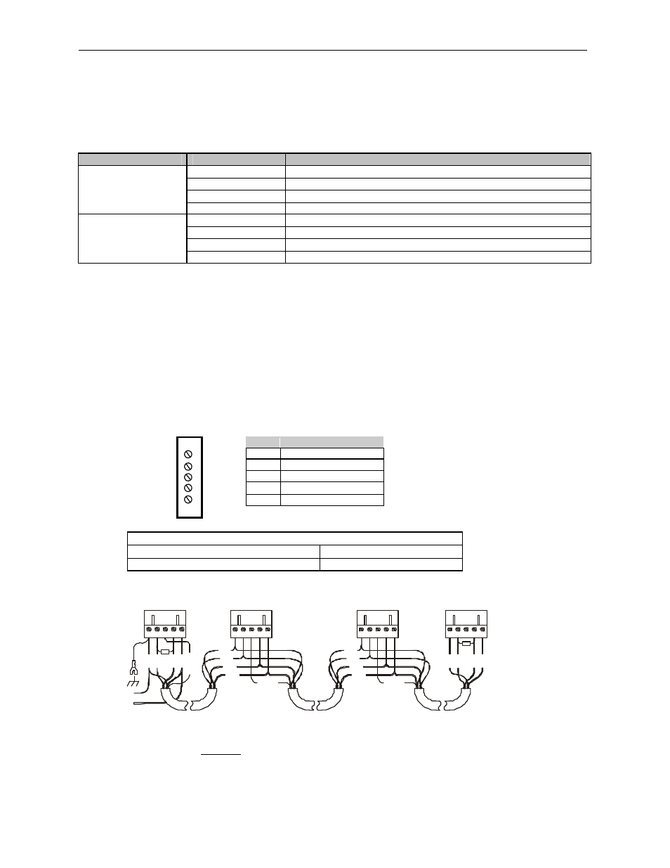
NETWORK CABLE
For detailed wiring information, refer to Chapter Two in the Control Station Hardware Manual
(MAN0227). A handy checklist is provided that covers panel box layout requirements and minimum
clearances.
Pin
Description
RED
1
V+
WHT
2
CAN_H
SHD
3
Shield
BLU
4
CAN_L
BLK
5
V-
Recommended Cable
Thick: (Max Distance = 500m)
Belden 3082A
Thin: (Max Distance = 100m)
Belden 3084A
CAN Wiring
Note: 12 - 24VDC must be supplied to the network.
RED
WHT
SHIELD
BLU
BLK
R
E
D
S
H
IE
L
D
RED
WHT
BLU
BLK
V
+
C
N
_
L
V
-
S
H
IE
L
D
1
2
1
Ω
C
N
_
H
V
+
C
N
_
L
V
-
S
H
IE
L
D
C
N
_
H
R
E
D
W
H
T
B
LU
B
LK
1
21
Ω
V
+
C
N
_
L
V
-
S
H
IE
L
D
C
N
_
H
R
E
D
W
H
T
B
LU
B
LK
RED
WHT
SHIELD
BLU
BLK
RED
WHT
BLU
BLK
V
+
C
N
_
L
V
-
S
H
IE
L
D
C
N
_
H
12-25VDC
+
-
001CAN002