Horner APG SmartStix HE559ADC970 User Manual
Page 5
ADC970
20 NOV 2003
Page 5
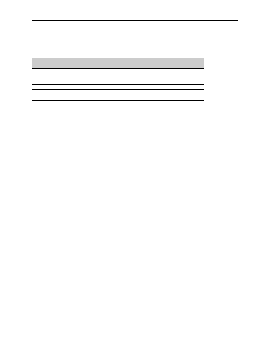
Each analog input on the HE550ADC970 has a single pole 345Hz (461uS) cutoff high frequency noise
filter. In addition a second digital filter may be specified in the first configuration word with the following
time constants.
Bit
15
14
13
Time Constant
0
0
0
10 milliseconds (Nominal hardware scan rate)
0
0
1
15 milliseconds
0
1
0
35 milliseconds
0
1
1
75 milliseconds
1
0
0
155 milliseconds
1
0
1
315 milliseconds
1
1
0
635 milliseconds
1
1
1
1.275 seconds
This digital filter is useful for applications with significant amounts of random noise. The slower time
constants, while yielding better noise suppression, take a longer time to settle after step changes and are
also sensitive to impulse noise which is treated like Gaussian noise and averaged.
Bit 16 of the first configuration word may be set to specify an adaptive filter algorithm that:
1. Responds much more quickly to large step changes at slower time constants with full filtering of low
level noise.
2. Suppresses impulse noise at the expense of slightly slower response at the shortest time constant
settings. (Approximately 10 additional milliseconds)
Note that actual system response time is network dependent.
See the SmartStix Programming Guide for more information.
6
INPUT CONVERSION FACTOR
The following table describes how real-world inputs are scaled into the controller. Given a known input
voltage or current, the register data value may be calculated by using the conversion factor from the
table. The following formula is used: Data = Voltage or Current In / Conversion Factor
Example:
The user selects a voltage range of ±5 V:
1.
The known input voltage is 3 VDC.
2.
Using the table, the conversion factor for the voltage range of ±5 V is .00015625.
3.
To determine the data value, the formula is used: Data = Vin / Conversion Factor
19200 = 3 VDC / 0.00015625